

Introduction
Music has been an integral part of our lives. It can soothe our souls, it can make us dance, and it can transform a moment into a memory. To truly experience the magic of music, a powerful and reliable audio system is essential. In this article, we will explore a 400W Amplifier Circuit Diagram, which utilizes the 2SC2922 and 2SA1216 transistors. We will also delve into the characteristics and applications of these transistors, as well as other relevant components such as the MJE350, MJE340, 2SA1266 transistors, and BZV85C24 diode.
The 400W amplifier circuit diagram is designed to deliver a high power output with excellent sound quality. It is suitable for professional audio applications, such as concerts, DJ setups, or home theaters. This circuit utilizes the 2SC2922 NPN power transistor and the complimentary 2SA1216 PNP power transistor to achieve the desired power output. It also employs several other components such as resistors, capacitors, and diodes to ensure stable performance.
The circuit consists of two stages – the pre-amplifier stage and the power amplifier stage. The pre-amplifier stage is responsible for amplifying the low-level input signal and providing the necessary signal gain. This stage is crucial as it sets the overall sound quality and determines the signal-to-noise ratio. The power amplifier stage, on the other hand, takes the amplified signal from the pre-amplifier stage and boosts it to the desired power level.
Circuit Diagram of 400W Amplifier Circuit Diagram
This 400w amplifier circuit diagram can be designed using a few basic components. The circuit diagram of this project is shown below.


More Circuit Layouts


Components List of 400W Amplifier Circuit Diagram
Following is the list of all components used in the 400w amplifier circuit diagram project:
Transistors
- 2SC2922 Transistor = 2
- 2SA1216 Transistor = 2
- MJE340 Transistor = 2
- MJE350 Transistor = 1
- 2SA1266 Transistor = 2
Capacitors
- 1uF Capacitor = 1
- 1nF Capacitor = 1
- 1n Capacitor = 1
- 220uF Capacitor = 1
- 47uF Capacitor = 1
- 2n2 Capacitor = 1
- 100uF Capacitor = 1
- 100N Capacitor = 1
Resistors
- 2.2k Resister = 2
- 100k Resister = 1
- 10k Resister = 2
- 3.3K Resister = 1
- 4.7K Resister = 1
- 300 ohms Resister = 3
- 270 ohms Resister = 1
- 33k Resister = 1
- 68 ohms Resister = 1
- 8.2k Resister = 1
- 330 ohms Resister = 1
- 10 ohms Resister = 5
- 0.1 ohm Resister = 4
Diodes
- BZV85C24 Diode = 1
- 1N4148 Diode = 3
- 2 Miscellaneous
Explanation of 400W Amplifier Circuit Diagram Components
The 2SC2922 transistor is a high-power NPN transistor specifically designed for audio amplifier applications. It can handle high collector currents of up to 15A and has a maximum power dissipation of 150W. The 2SC2922 exhibits excellent linearity and low distortion, making it ideal for high-fidelity audio amplification. Its high current and voltage capabilities make it suitable for driving large speakers or subwoofers.
The 2SA1216 transistor is a complementary PNP transistor to the 2SC2922. It complements the function of the 2SC2922 by handling the negative half of the audio waveform. The 2SA1216 has similar specifications as the 2SC2922, with a maximum collector current of 15A and a maximum power dissipation of 150W. Together, the 2SC2922 and 2SA1216 form a robust and stable power amplification stage.
To ensure reliable and efficient operation of the amplifier, additional components such as the MJE350 and MJE340 transistors are employed. The MJE350 and MJE340 are high-voltage, high-speed NPN and PNP transistors, respectively. These transistors provide voltage regulation and protection for the audio amplifier circuit. They prevent voltage spikes, short circuits, and thermal runaway, ensuring the longevity and safety of the amplifier.
The 2SA1266 transistor is a silicon PNP epitaxial transistor designed for low-frequency amplifier applications. While not directly involved in the power amplification stage, the 2SA1266 is used in the pre-amplifier section of the circuit to provide signal amplification and shaping. It is a versatile transistor with a maximum collector current of 0.7A and a maximum power dissipation of 0.9W.
The BZV85C24 is a 24V Zener diode used for voltage regulation. It ensures stable operating voltages for the various stages of the amplifier circuit. The BZV85C24 diode exhibits excellent voltage stability and low reverse leakage current, making it an ideal choice for this application.
Conclusion of 400W Amplifier Circuit Diagram
The 400W amplifier circuit diagram utilizing the 2SC2922 and 2SA1216 transistors is a powerful and reliable audio solution. It delivers high-quality sound, making it suitable for professional audio applications. The 2SC2922 and 2SA1216 transistors, along with the MJE350, MJE340, 2SA1266, and BZV85C24 diode, ensure stable performance, protection, and voltage regulation. By understanding the characteristics and applications of these components, you can build and enjoy a powerful audio system that transforms music into a captivating experience.
More projects, You may like:
- Video Transmitter DIY Homemade FM Radio Transmitter
- Adjustable Power Supply DIY Battery Charger
- 12V-220V 500 Watt inverter DIY Homemade
- 12V-220V H-Bridge Inverter DIY Homemade
- MPPT Solar Charge Controller DIY Homemade
- 18650 battery bank free charge protection module
- D718 B688 Bass Amplifier Homemade DIY
- C5200 Bass Amplifier DIY Homemade with Volume
- DIY LA4440 bass amplifier homemade
- C5200 A1943 TDA2030 Amplifier DIY Homemade
For more project and circuit diagrams, you can go through the Schematics in the main menu where you can find many interesting projects and circuit diagrams like audio amplifier circuits, voltage booster circuit, battery charger circuit and timer circuits etc., which are all beginner circuit projects. Feel free to check them out!

Thank you for visiting the article.
You may also like:
![Non-Inverting AC Power Amplifier Circuit Diagram]()
Non-Inverting AC Power Amplifier Circuit Diagram
![TDA2030 Bass Amplifier Circuit using BD907 & BD908]()
TDA2030 Bass Amplifier Circuit Diagram using BD907 & BD908
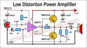
![Low Distortion Power Amplifier Circuit Diagram]()
Low Distortion Power Amplifier Circuit Diagram
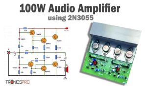
![100W Audio Amplifier Circuit Diagram using 2N3055 IC 2]()
100W Audio Amplifier Circuit Diagram using 2N3055
![Bass Amplifier Circuit using 2SC5200 & TDA2030]()
Bass Amplifier Circuit Diagram using 2SC5200 & TDA2030
![30W Stereo Amplifier TDA7297]()
30W Stereo Amplifier TDA7297 DIY Circuit
![200W Amplifier Circuit Diagram using Sanken 2SC2922 & 741 IC]()
200W Amplifier Circuit Diagram using Sanken 2SC2922 & 741 IC
![Instrumentation amplifier single supply circuit diagram]()
Instrumentation Amplifier Single-Supply Circuit


I tried and it’s a powerful one
Thanks for the comments.