

Introduction
Having a reliable power source that can deliver variable voltage and current is of great importance in the field of electronics. A variable power supply enables an electronic engineer to work on different circuits and components that require different voltages and currents. In this article, we will discuss the design of a Variable Power Supply 0-30V_10A using dual 2N3055 transistors, LM317, BD139, A/V Meter and two Potentiometers to control amperes & volts. A step by step project video is also provided here which will guide you assembling this power supply easily.
The circuit of this Variable Power Supply 0-30V_10A is built using commonly available electronic components. It is a regulated power supply, which means that the output voltage and current are constant, regardless of changes in the input voltage or load. The design uses dual 2N3055 transistors to handle the high current flow, while LM317 is used to regulate the output voltage.
Circuit Diagram of Variable Power Supply 0-30V_10A
This Variable Power Supply can be designed using a few basic components. The circuit diagram of this project is shown below.

Variable Power Supply Schematic

More Circuit Layouts


Components List of Variable Power Supply 0-30V_10A
Following is the list of all components used in this project:
- 2N3055 Transistor x 2
- LM317 Regulator IC x 1
- BD139 Transistor x 1
- 7805 Regulator IC x 1
- 0.1uf (104J) Capacitor x 3
- 0.33 Ohms / 5 Watts Resister x 2
- 1k Resister x 1
- 220 Ohms Resister x 1
- 10k Potentiometer x 1 with knob
- 5k Potentiometer x 1 with knob
- 0-30 Volts Digital A/V Meter x 1
- 12 Volts On/Off Switch x 1
- LED x 1
- 4mm Banana Connector Socket x 1 Pair
- 12v-0v-12v 5 to 10A Transformer – (As required)
- 6-10A Bridge Rectifier
- 6800uf / 50v Capacitor
- 104J / 0.01uf Capacitor
Explanation of Variable Power Supply 0-30V_10A
The two potentiometers are used to control the output voltage and current. These potentiometers divide the voltage and current, respectively, and adjust the output based on the user’s setting. The BD139 transistor helps in protecting the circuit from short circuits and overloads.
The A/V meter displays the output voltage and current, making it easier for the user to monitor the power supply’s performance. It also helps in preventing the circuit from damage that may result from an overload.
This Variable Power Supply design can be used in different applications, such as testing electronic circuits, powering up different electronic devices, and measuring electronic components’ characteristics.
In the next section, we will discuss the details of the circuit components and how they contribute to the Variable Power Supply’s operation.
Circuit Components used in Variable Power Supply 0-30V_10A
The following components are used to build the Variable Power Supply 0-30V_10A:
- Transformer: The transformer is used to adjust the input voltage to the required level. The input voltage can range from 110V to 220V AC, and the output voltage can be varied from 0 to 30V DC.
- Rectifier diodes: The rectifier diodes are used to convert the AC input voltage to DC voltage. In this design, four rectifier diodes are used.
- LM317 regulator: The LM317 is used to regulate the output voltage of the power supply. It is a three-pin adjustable regulator that can regulate the output voltage from 1.2V to 37V. In this design, LM317 is used to regulate the output voltage from 0V to 30V.
- Dual 2N3055 transistors: The transistors are used to amplify the current flow in the circuit. They are used to handle the high current flow, up to 10A. The transistors are mounted on a heat sink to prevent them from overheating.
- BD139 transistor: The BD139 transistor is used to protect the circuit from short circuits and overloads. It is connected in series with the output voltage, and its base is connected to the output current. Whenever the output current exceeds the set limit, the transistor will switch off, protecting the circuit from damage.
- Potentiometers: The two potentiometers are used to control the output voltage and current. The Voltage Potentiometer adjusts the output voltage, while the Current Potentiometer adjusts the output current. These potentiometers function by dividing the output voltage or current, depending on the setting.
- A/V Meter: The A/V meter is used to display the output voltage and current. It helps the user in monitoring the Variable Power Supply’s performance and preventing the circuit from damage that may result from an overload.
Conclusion
Having a reliable Variable Power Supply is of utmost importance in the field of electronics. It enables an electronic engineer to work on different circuits and components that require different voltages and currents. In this article, we discussed the design of a Variable Power Supply 0-30V_10A, using dual 2N3055 transistors, LM317, BD139, A/V Meter and two Potentiometers to control amperes & volts.
The design of this Variable Power Supply is built using commonly available electronic components. It is a regulated power supply, which means that the output voltage and current are constant, regardless of changes in the input voltage or load. The two potentiometers are used to control the output voltage and current, while the BD139 transistor helps in protecting the circuit from short circuits and overloads.
This Variable Power Supply design can be used in different applications, such as testing electronic circuits, powering up different electronic devices, and measuring electronic components’ characteristics. The A/V Meter displays the output voltage and current, making it easier for the user to monitor the power supply’s performance and prevent damage that may result from an overload.
Overall, the Variable Power Supply 0-30V_10A is a reliable and efficient design that can provide the required voltage and current to different electronic circuits and devices. Its simplicity makes it easily modifiable, and thereby, can conform to different requirements of various projects.
More projects, You may like:
- Video Transmitter DIY Homemade FM Radio Transmitter
- Adjustable Power Supply DIY Battery Charger
- 12V-220V 500 Watt inverter DIY Homemade
- 12V-220V H-Bridge Inverter DIY Homemade
- MPPT Solar Charge Controller DIY Homemade
- 18650 battery bank free charge protection module
- D718 B688 Bass Amplifier Homemade DIY
- C5200 Bass Amplifier DIY Homemade with Volume
- DIY LA4440 bass amplifier homemade
- C5200 A1943 TDA2030 Amplifier DIY Homemade

You may also like:
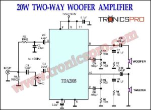
![20W Two-Way Woofer Amplifier TDA2005 Circuit Diagram]()
20W Two-Way Woofer Amplifier TDA2005 Circuit
![TDA2030 Stereo Amplifier Circuit Diagram]()
TDA2030 Stereo Amplifier Circuit Diagram
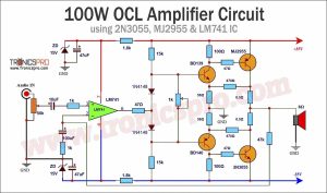
![100W OCL Amplifier Circuit Diagram using 2N3055 & LM741 IC]()
100W OCL Amplifier Circuit Diagram using 2N3055 & LM741 IC
![170W Bridge Amplifier TDA7294 Circuit Diagram]()
170W Bridge Amplifier TDA7294 Circuit Diagram
![120W MOSFET Amplifier Circuit using IRF240 & IRF9240]()
120W MOSFET Amplifier Circuit Diagram using IRF240 & IRF9240
![150W Audio Amplifier Circuit Diagram using 2N3055 Transistors]()
150W Audio Amplifier Circuit Diagram using Dual 2N3055 Transistors
![Stereo Amplifier NE5532 Circuit Diagram]()
Stereo Amplifier NE5532 Circuit Diagram
![TDA2030 Subwoofer Amplificer Circuit with 4558 IC]()
TDA2030 Subwoofer Amplificer Circuit Diagram with 4558 IC


Can we replaced 2N3055 with TIP3055.
Yes, I have been using this with TIP3055. Works flawlessly.
Can you send me DIY projects diagram book
Sorry dear. I don’t have any book right now.
Thanks for visiting the site and comments.
Can I use transformer 300VA 24V (2x12V)?
This project not working
It works well. Check your connections repeatedly.
Thanks for comments.
a parts list would help beginners
Thanks for reminder. I will do it.
Však v článku je zoznam komponentov.
Starám sa o svojich návštevníkov a ďakujem aj vám.
5W resistor will overheat when current gets 5A
P=5*5*0.33=8.25W
I mean the maximum is about 7,6 amps is it not?
the transistors are in parrallel so they should split the load
What and where is the display chip from?
As ligaçoes estao coretas?a ligaçao cabo amarelo displai tensao nao deveria estar ligado na saida da fonte (+ v out)?
Hi ,the circuit is not getting to zero volt ,the minimum voltage is 1.2v .could you advise what should be done or what could be the problem.
Thank you
2N3055 are out of production and obsolete any other transistor with that wording nowadays is a fake
It is really disappointing to know that most of the circuits given on internet are just to get likes and it is simply disgraceful… I tried to make this circuit and I tried very hard and this power supply 0 to 30 volt, I checked it again and again but it did not give me any Joy. The point is not that I wasted money but I wasted a lot of my valuable time. Mostly the circuits are neither tried not tested… All b******* and rubbish.
This is a video project and the link was provided in the first paragraph of this article. You can watch it step by step. The project works well. You have done some mistakes for sure.
Sir what is the output status if pot become open during operation, it is a compulsory thing we should aware of.
I think that voltmeter is not correctly connected, it must be connected to the +V terminal, not bases junction
From: Iran:
Yes. It must be connected to the common connection of the resistors taken from the emitters of the transistors.