

The video-based article, how to make an ultra bass 100 watts mono class-AB d718 b688 powerful amplifier using 2n3904 transistors in the audio section. A combination of d718 b688 powerful amplifiers is widely used for high gain. You must use transistor insulation (Mica) to prevent touching the heat sink to avoid short circuits because both transistors are using opposite currents.
DIY homemade amplifiers are a great way for beginners and students to get into the world of audio. By following some simple steps, you can create your own amplifier with parts that won’t cost an arm and a leg. You’ll need basic electronic components including transistors, resistors, capacitors, and transformers. Plus, you’ll have to source some parts locally as well, such as speaker wires, connectors, and power supplies. It’s worth noting that while building your own amplifier can be fun and creative, it’s important to make sure you understand how electricity works in order to avoid creating any dangerous situations. With everything in place, you’re pretty much good to go – now just plug in your favorite instrument or device and listen to the awesome sound of it coming through your custom-made amplifier!

Following is the related YouTube video of this project – it’s an awesome demonstration of how my project turns ideas into reality. In the video, you can see a vibrant and creative team in action, as they go from initial concept sketches to working prototypes in no time flat. The custom project development process is broken down step by step, which makes it easy to follow. There are even some helpful tips showcased throughout the video – great for anyone looking to become an even better developer! So watch right now and get inspired!
I have chosen this circuit with very few components which are quite easy to assemble for beginners and students. I strongly recommend choosing a large enough and thick heat sink for enough heat dissipation for the safety of both transistors. The components list is also provided at the end of this article which is easy to find in the local market.
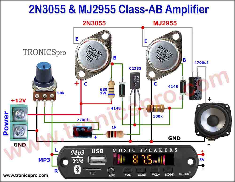
Circuit Diagram
Following is the Circuit Diagram of the D718 B688 Powerful Amplifier with Volume Bass and Treble Tone Control. This circuit diagram represents a project that involves the use of basic and cheap electronic components. This is a great way for someone with basic wiring knowledge to create something interesting and effective!


List of Components
used in D718 B688 Powerful Amplifier
| Type | Value | Quantity |
|---|---|---|
| Transistor | D718 | 1 |
| Transistor | B688 | 1 |
| Transistor | 2N3904 | 1 |
| Capacitor | 1N4007 | 2 |
| Capacitor | 2200 uF | 1 |
| Capacitor | 4.7 uF | 1 |
| Capacitor | 104 | 4 |
| Resister | 0.33 Ohms | 2 |
| Resister | 1k Ohms | 3 |
| Resister | 2.2k ohms | 2 |
| Resister | 100k | 1 |
| Resister | 50k | 3 |
| Heat Sink | Solid | 1 |
| Power Supply Socket | – | 1 |
| Mobile Jack | 3.5 mm | 1 |
| Power Supply | 12 volts | 1 |
| Speaker | 4 ohms | 1 |
Development Images
of D718 B688 Powerful Amplifier DIY
Step # 1
Tighten D718 & B688 transistors onto the heat sink with proper insulation (MICA). Be sure the back plate of both transistors should not be touched with a heat sink. Join plus & minus sides of the two diodes 1N4007 together. Solder one positive end of the right diode with Base Pin.1 of right transistor B688. And another negative of the left diode with Base Pin.1 of the left transistor D718. Connect two 0.33 ohms/5w resistors to Emitters Pin.3 of both transistors. Join the other ends of both transistors together.

Step # 2
Solder the Collector of 2N3904 Transistor to the Bass of B688 and Emitter of 2N3904 Transistor to Collector of B688. Also, solder a 100k resistor to the base of the 2N3904 Transistor and the center joint of 0.33 ohms/5w resistor.

Step # 3
Connect the negative side of the 4.7uf capacitor to the base of the 2N3904 Transistor.

Step # 4
Solder negative end of 2200uf/50v capacitor to the center joint of two 0.33 ohms resisters. Also, solder 1k resister’s one end to the base of D718 and the other end to the positive side of 2200uf/50v capacitor.

Step # 5
I did not show the working of the bass-treble circuit here. For more detail to see bass-treble [Click Here]. Connect the positive pin of the 4.7uf capacitor to Center Pin.2 of volume control.

Step # 6
Take one 0.47 ohms/5w resister and also take 0.6mm copper enameled wire. Wrap the around the resister 12 times and solder both ends with both ends of the resister.

Step # 7
Now solder one end of the resister coil to the collector Pin.2 of the D718 transistor. Attach red positive wire of the power supply to the center pin Collector of the D718 transistor and the black negative wire of the power supply to the center pin Collector of the B688 transistor.

Step # 8
It’s time to attach a 3.5mm mobile jack. Solder both left & right audio output wires to Pin.1 of the Bass Controller and ground wire to Pin.3 of the volume controller. Also Join Pin.3 of the Volume Controller Collector, the center pin of the B688 transistor which is ground.

Step # 9
Connect Speaker’s positive to the resister coil’s empty end. The speaker’s negative will go to the +ve connection of the 2200Uf Capacitor.

Connect the jack pin to the mobile. Turn the power supply On, play music with your mobile, and Enjoy. Thank you so much for visiting this site.
Conclusion
Making a DIY homemade amplifier can be an incredibly rewarding experience. Not only does it provide you with the satisfaction of knowing that you were able to construct something entirely from scratch, but it also often allows for significant cost savings when compared to purchasing pre-made amplifiers. In order to build your own amplifier successfully, it is important to have the right tools, materials, and resources at your disposal. Additionally, patience and careful attention to detail will ensure that you receive optimal performance from your amplifier. Once the construction is completed, testing should be carried out in order to guarantee that everything works correctly before using the finished product.
You may also like:
![C5200 A1943 JRC4558 amplifier DIY homemade]()
C5200 A1943 JRC4558 amplifier DIY homemade
![D718 amplifier DIY homemade]()
DIY homemade D718 amplifier ultra bass
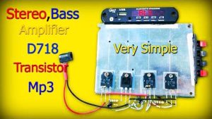
![D718 stereo bass amplifier with MP3 Bluetooth]()
D718 Stereo Bass Amplifier with MP3 Bluetooth
![DIY C5200 A1943 amplifier homemade]()
DIY C5200 A1943 amplifier homemade
![C5200 Stereo Bass Amplifier DIY Volume Bass Treble]()
C5200 Stereo Bass Amplifier DIY Volume Bass Treble
![Stereo Amp Thumbnail New]()
DIY D718 stereo amplifier homemade
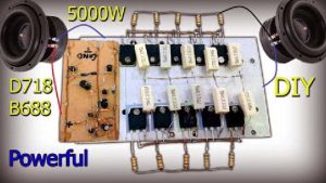
![D718 B688 Amplifier DIY Powerful Ultra Bass]()
D718 B688 Amplifier DIY Powerful Ultra Bass
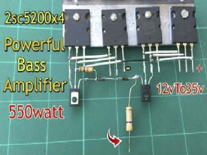
![C5200 Powerful Bass Amplifier DIY Homemade]()
C5200 Powerful Bass Amplifier DIY Homemade


hello, good morning I could increase this capacitor, it would give more power to the amplifier
A little bit will increase. Better you increase voltage to increase power. Thanks.
Thank you so much dear.
can i use 48vcd 3a?
I have tis amplifier can I replace the power transistors with MOSFET to use 40-040 8 amp transformer.
Thank you and I have made one and sounds good
Thank you.
lohice andaperomecalientamuchoel718 quepuedeser el688 estafrio
Thank you.
what maximum voltage can I use
In your write up step 9, you incorrectly state that the negative of the speaker goes to Ground.
Step # 9
Connect Speaker’s positive to the resister coil’s empty end. Speaker’s negative will go to ground
That is incorrect and just releases the magic smoke from the speaker. The -ve speaker connection is to the +ve connection of the 2200Uf Capacitor which you correctly show in the video and the schematic.
Thank you so much for correction in sentence. Your response is highly appreciated.