
120W Amplifier Circuit Diagram using 2SC5200 & 2SA1943 Apex Kelvin AX14. This circuit design offers powerful amplification capabilities while maintaining a high level of sound clarity.

120W Amplifier Circuit Diagram using 2SC5200 & 2SA1943 Apex Kelvin AX14. This circuit design offers powerful amplification capabilities while maintaining a high level of sound clarity.

The 120W Power Amplifier Circuit Diagram using 2SC5200 in the output section, TIP122, TIP127 in the driver section and TL071 IC in the preamplifier section is a reliable and efficient circuit that can deliver high-quality audio output.

One common type of power amplifier circuit is the one with active tone control, which allows for adjustment of the frequency response of the audio signal.

A 500W power amplifier circuit diagram using 2SC5200 & 2SA1943 is a high-performance amplifier design that promises to deliver impressive audio quality with its powerful output.
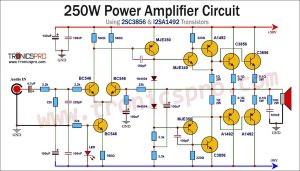
The 250W power amplifier circuit using 2SC3856, 2SA1492, MJE340, MJE350, and BC546 transistors is an effective and reliable choice for electronic devices requiring high-quality audio output.

The 100W audio amplifier circuit using TIP3055, TIP2955, BC546, and BC557 transistors is a reliable and efficient option for audio amplification. With its high power output and low distortion, it is suitable for driving speakers in various audio applications.

The 150W OCL amplifier circuit diagram described in this article is a high-quality and powerful component that is essential for any audio system requiring loud and clear sound. By utilizing transistors such as the 2N3055, BD139, BD140, and 2SA733, this amplifier is capable of delivering strong and distortion-free audio output.

The 100W MOSFET Amplifier Circuit Diagram using 2SK134 & 2SJ49 is a powerful and efficient circuit that can deliver high-quality audio output. This circuit utilizes high-quality components such as 2SK134 & 2SJ49 in the output section, 2SD666 & 2SB646 in the driver section, and 2SA1016 in the preamplifier section.

In this article, we will discuss a 600W audio power amplifier circuit diagram that utilizes 2SC5200 & 2SA1943 transistors in the output section, along with other transistors like MJE340, MJE350, MPSA42, MPSA92 in the driver section and 2N5551 in the preamplifier section.

The 120W MOSFET amplifier circuit diagram featuring IRFP240 & IRFP9240 offers a high-quality audio performance with low distortion and high power output.

 Variable Power Supply 0-30V_10A Circuit Diagram
 C5200 A1943 TDA2030 Amplifier DIY Homemade
 DIY LA4440 bass amplifier homemade
 Bass Tone Control Circuit Diagram – TRONICSpro
 2N3055 stereo amplifier homemade bluetooth diy
 500W Power Amplifier Circuit using c5200 a1943
 DIY bass treble volume homemade Tone Control
 Subwoofer Amplifier Circuit Diagram using TDA2030
 KSP92 Pinout, Equivalent Application Datasheet
 KSP44 Pinout, Equivalent Application Datasheet
 MPSA92 Pinout, Equivalent Application Datasheet
 MPSA42 Pinout, Equivalent Application Datasheet
 PN200 Pinout, Equivalent Application Datasheet
 PN100 Pinout, Equivalent Application Datasheet
 MJE802 Pinout, Equivalent Application Datasheet
 MJE800 Pinout, Equivalent Application Datasheet