Introduction
Owning a car brings convenience and mobility, but it also comes with the responsibility of maintaining its battery life. A dead battery can leave you stranded, so having a reliable 12V auto battery charger is essential. In this article, we will guide you through the process of building your own homemade auto battery charger using commonly available electronic components such as the LM358 IC and BC547 Transistor.
Introduction to Major Parts:
What is LM358 IC?
The LM358 IC is a widely used operational amplifier integrated circuit. It is ideal for applications requiring low power consumption, high voltage gain, and wide input and output voltage ranges. The LM358 features two independent, high-gain, internally frequency-compensated operational amplifiers that can operate from a single power supply.
The IC is designed to be directly powered with a wide supply voltage range of 3V to 32V, making it suitable for various applications, including battery charging systems. With its low quiescent current of around 300-400 µA, it is perfect for energy-efficient projects.
What is BC547 Transistor?
The BC547 is a popular NPN general-purpose bipolar junction transistor. It is commonly used in switching and amplification circuits due to its high current gain, low voltage, and current requirements. The BC547 transistor can handle a maximum collector current of 100mA, making it suitable for low-power applications like our battery charger.
The BC547 transistor has three terminals— the emitter, base, and collector. By controlling the current flowing through the base terminal, we can control the current flowing between the emitter and collector terminals. This property allows us to regulate the charging process and implement an auto cut off mechanism.

Circuit Diagram of 12V Auto Battery Charger
This project can be designed using a few basic components. The circuit diagram of this project is shown below.

More Circuit Layouts


Components List of 12V Auto Battery Charger
Following is the list of all components used in this project:
- 1X LM358 IC
- 1X BC547 TRANSISTOR
- 1X 3V ZENER DIODE
- 2X 1N4148 DIODES
- 2X LED
- 1X 10K TRIMPOT
- 2X 1K RESISTORS
- 3X 10K RESISTORS
- 1X 12V RELAY
- 2X 2 PIN TERMINAL BLOCK
- 1X PERF BOARD
- JUMPER WIRES
Explanation of 12V Auto Battery Charger
Building the 12V Auto Battery Charger Project:
Now that we understand the key components, let’s proceed with building our homemade 12V auto battery charger with auto cut off feature.
Gather all the components as per the list of material provided above in the Components List section and then connect them according to the circuit diagram provided above for your ready reference.
Circuit Diagram and Working Principle:
To start, let’s take a look at the above circuit diagram of our 12V auto battery charger:
The LM358 IC acts as the heart of the circuit, functioning as a comparator. The battery charger’s working principle revolves around monitoring the voltage of the battery being charged. If the battery voltage surpasses a certain threshold, the charger automatically cuts off the charging process to prevent overcharging.
The charger includes a voltage divider network consisting of resistors R1, R2, and R3. This network is responsible for setting the threshold voltage level at which the charger will cut off the charging process. The choice of resistor values depends on the desired threshold voltage.
The voltage at the junction of R2 and R3 is fed to the non-inverting terminal of the LM358 IC, while the inverting terminal receives a fixed voltage reference. When the battery voltage rises above the threshold level, the non-inverting terminal’s voltage becomes higher than the reference voltage, triggering the LM358 to provide a high output.
This high output activates the BC547 transistor, allowing current to flow through the base terminal and onto the charging circuit. The charging current passes through the diode and resistor R5, limiting the current to a safe value.
Once the battery voltage drops below the threshold level, the LM358’s output goes low, deactivating the BC547 transistor and cutting off the charging circuit. This auto cut off mechanism ensures that the battery is neither overcharged nor left uncharged.
Conclusion of 12V Auto Battery Charger
Building a homemade 12V auto battery charger with an auto cut off feature using the LM358 IC and BC547 transistor is an easy and simple electronics project suitable for beginners. It allows you to monitor and maintain your car’s battery life effectively.
Remember to select the appropriate resistor values to set the desired threshold voltage based on your battery specifications. Safety should always be a priority when working with electrical components, so be cautious and follow standard practices while assembling the circuit.
With this homemade auto battery charger, you can now ensure that your car battery remains in good condition, reducing the risk of untimely breakdowns. Enjoy the convenience and peace of mind that comes with a fully charged battery!
More projects, You may like:
- Video Transmitter DIY Homemade FM Radio Transmitter
- Adjustable Power Supply DIY Battery Charger
- 12V-220V 500 Watt inverter DIY Homemade
- 12V-220V H-Bridge Inverter DIY Homemade
- MPPT Solar Charge Controller DIY Homemade
- 18650 battery bank free charge protection module
- D718 B688 Bass Amplifier Homemade DIY
- C5200 Bass Amplifier DIY Homemade with Volume
- DIY LA4440 bass amplifier homemade
- C5200 A1943 TDA2030 Amplifier DIY Homemade
For more project and circuit diagrams, you can go through the Schematics in the main menu where you can find many interesting projects and circuit diagrams like audio amplifier circuits, voltage booster circuit, battery charger circuit and timer circuits etc., which are all beginner circuit projects. Feel free to check them out!
Thanks for visiting the article and wat
You may also like:
![12V Battery Overcharge Protection DIY Homemade]()
12V Battery Overcharge Protection DIY Homemade
![How to Make Police Chaser DIY]()
How to Make Police Chaser DIY - TRONICSpro
![How to Make Battery Tester DIY Homemade]()
How to Make Battery Tester DIY Homemade
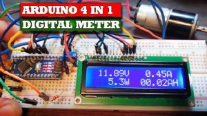
![Adruino 4-In-1 Digital Meter Volt-Amp-Watt-AH]()
Adruino 4-In-1 Digital Meter Volt-Amp-Watt-AH
![Reverse Polarity Protection Circuit]()
Reverse Polarity Protection Circuit Diagram
![Wireless Water Level Controller DIY Homemade]()
Wireless Water Level Controller DIY Homemade
![CNC Plotter DIY Homemade Thumbnail]()
CNC Plotter DIY Homemade - TRONICSpro
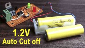
![How to Make 1.2V Automatic Battery Charger]()
How to Make 1.2V Automatic Battery Charger