Introduction
In electronic circuits, regulated power supply plays a crucial role in ensuring stable and reliable voltage levels for various components. One effective method of achieving this stability is by using an operational amplifier for voltage comparison and regulation. This article presents a practical Regulated Power Supply circuit diagram utilizing the popular operational amplifier type 741, along with 2n2955 and BC108 transistors, to create a regulated power supply. The circuit utilizes a zener diode to control the current flow, resulting in minimized noise and enhanced voltage stability. The operational amplifier acts as a voltage comparator, maintaining close regulation by amplifying the difference between the input and reference voltages.
Regulated Power Supply Circuit Diagram
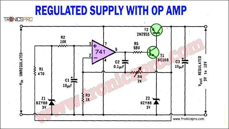
This project can be designed using a few basic components. The circuit diagram of this project is shown below.
More Circuit Layouts


Components List of Regulated Power Supply Circuit
Following is the list of all components used in this project:
- 741 Op-amp IC x 1
- 2N2955 PNP Transistor x 1
- BC108 Transistor x 1
- BZY88-3V Zener Diode x 1
- 10uf Capacitor x 2
- 0.1uf Capacitor x 1
- 2K Variable Resister x 1
- 10k Resister x 1
- 470 Ohms Resister x 1
- 680 Ohms Resister x 1
- 1k Resister x 1
Working Explanation
A practical circuit using an operational amplifier for voltage comparison and regulation is shown in the following circuit diagram. In this case, the current for the zener diode is taken from the regulated supply rather than the unregulated supply. This minimizes noise and increases voltage stability. Zener current is decided by resistor R1.
A popular commonly available type of operational amplifier type 741 is used for comparison of voltages. The full zener voltage is applied to the non-inverting input of the op amp 741, while a fraction of the output voltage, as decided by the voltage divider R4 and R3 is applied to the inverting input of the op amp. If input to the (+) input is higher than that at the (-) input terminal, the positive going output of the op amp makes T1 conduct more and that increases the output voltage. The reverse happens if the voltage at (+) input is lower than that at the (-) input. The high gain of the operational maintains close regulation.
Conclusion:
The regulated power supply circuit using the operational amplifier 741, 2n2955, and BC108 transistors provides an effective solution for maintaining stable voltage levels in electronic circuits. By utilizing the operational amplifier as a voltage comparator, the circuit ensures precision in voltage regulation. The inclusion of the zener diode, along with resistor R1, further enhances voltage stability and minimizes noise. The high gain of the operational amplifier guarantees precise regulation, making it an ideal choice for various applications. This regulated power supply circuit serves as a reliable and efficient solution for meeting voltage requirements in electronic devices and systems.
More projects, You may like:
- Video Transmitter DIY Homemade FM Radio Transmitter
- Adjustable Power Supply DIY Battery Charger
- 12V-220V 500 Watt inverter DIY Homemade
- 12V-220V H-Bridge Inverter DIY Homemade
- MPPT Solar Charge Controller DIY Homemade
- 18650 battery bank free charge protection module
- D718 B688 Bass Amplifier Homemade DIY
- C5200 Bass Amplifier DIY Homemade with Volume
- DIY LA4440 bass amplifier homemade
- C5200 A1943 TDA2030 Amplifier DIY Homemade
For more project and circuit diagrams, you can go through the Schematics in the main menu where you can find many interesting projects and circuit diagrams like audio amplifier circuits, voltage booster circuit, battery charger circuit and timer circuits etc., which are all beginner circuit projects. Feel free to check them out!

Thank you for visiting the article.


