


Introduction
A power amplifier is an electronic device used to amplify the power of a signal, typically from a low-power source such as a microphone or a pre-amplifier, to a level suitable for driving loudspeakers or other high-power loads. A 100W power amplifier circuit is a popular choice among audio enthusiasts due to its ability to deliver high-quality sound reproduction and adequate power output. In this article, we will discuss a circuit diagram for a 100W power amplifier using TIP142, TIP147, TIP41, and two BC556 transistors. We will also provide specifications for each of these transistors.
100W Power Amplifier Circuit Diagram
The circuit diagram for the 100W power amplifier is fairly straightforward, utilizing a combination of five powerful transistors. The TIP142 and TIP147 are darlington transistors, while the TIP41 is a general-purpose NPN transistor. The pair of BC556 is a PNP transistor commonly used in audio amplifier circuits. The following diagram illustrates how these transistors are interconnected to form the power amplifier circuit.


More Circuit Layouts


Components List of 100W Power Amplifier Circuit
Following is the list of all components used in this project:
- TIP142 Darlington NPN Transistor x 1
- TIP147 Darlington PNP Transistor x 1
- TIP41 Darlington NPN Transistor x 1
- BC556 PNP Transistor x 2
- 0.33Ω – 5W Resister x 2
- 3.3kΩ – 1W Resister x 1
- 22kΩ Resister x 2
- 220Ω Resister x 1
- 33Ω Resister x 1
- 27kΩ Resister x 1
- 10uF Capacitor x 2
- 100uF Capacitor x 1
- 1N4007 Diode x 2
- Speaker 4Ω to 8Ω
- Power Supply 24V to 35V Symmetrical (Dual)
Working Explanation of 100W Power Amplifier Circuit
The input signal is first amplified by the BC556 transistor, acting as a pre-amplifier, and then passed on to the darlington transistors for further amplification. The TIP142 and TIP147 transistors are configured in a complementary pair, with the TIP142 being an NPN transistor and the TIP147 being a PNP transistor. This configuration ensures balanced amplification of both positive and negative halves of the input signal. The TIP41 transistor acts as a driver for the darlington pair, providing the necessary current gain.
Specifications of TIP142 Transistor:
- Transistor Type: NPN Darlington
- Maximum Collector-Emitter Voltage: 100V
- Maximum Collector Current: 10A
- Maximum Power Dissipation: 125W
- DC Current Gain (hFE): 1000 (min)
- Package Type: TO-247
Specifications of TIP147 Transistor:
- Transistor Type: PNP Darlington
- Maximum Collector-Emitter Voltage: 100V
- Maximum Collector Current: 10A
- Maximum Power Dissipation: 125W
- DC Current Gain (hFE): 1000 (min)
- Package Type: TO-247
Specifications of TIP41 Transistor:
- Transistor Type: NPN
- Maximum Collector-Emitter Voltage: 100V
- Maximum Collector Current: 6A
- Maximum Power Dissipation: 40W
- DC Current Gain (hFE): 40-160
- Package Type: TO-220
Specifications of BC556 Transistor:
- Transistor Type: PNP
- Maximum Collector-Emitter Voltage: -65V
- Maximum Collector Current: -100mA
- Maximum Power Dissipation: 500mW
- DC Current Gain (hFE): 80-600
- Package Type: TO-92
Conclusion of 100W Power Amplifier Circuit
The 100W power amplifier circuit using transistors is an effective design for audio enthusiasts looking for a high-powered amplifier with excellent sound quality. The darlington transistors, TIP142 and TIP147, provide a significant current gain, allowing for efficient amplification of the input signal. The TIP41 transistor acts as a driver for the darlington pair, ensuring stable and reliable operation. The BC556 transistor serves as a preamplifier, further enhancing the audio signal before being amplified by the power transistors.
It is important to note that while this circuit diagram provides a solid foundation for a power amplifier, additional components such as a power supply, heat sinks, and protection circuits may be necessary to ensure optimal performance and safety. Furthermore, it is always recommended to follow proper safety precautions and consult expert guidance when working with high-power electronic circuits.
In conclusion, the 100W power amplifier circuit using TIP142, TIP147, TIP41, and BC556 transistors is a reliable and efficient solution for audio enthusiasts seeking a powerful amplifier with excellent sound reproduction. By understanding the specifications and proper configuration of each transistor, one can build a high-quality power amplifier capable of delivering impressive audio performance.
More projects, You may like:
- Video Transmitter DIY Homemade FM Radio Transmitter
- Adjustable Power Supply DIY Battery Charger
- 12V-220V 500 Watt inverter DIY Homemade
- 12V-220V H-Bridge Inverter DIY Homemade
- MPPT Solar Charge Controller DIY Homemade
- 18650 battery bank free charge protection module
- D718 B688 Bass Amplifier Homemade DIY
- C5200 Bass Amplifier DIY Homemade with Volume
- DIY LA4440 bass amplifier homemade
- C5200 A1943 TDA2030 Amplifier DIY Homemade
For more project and circuit diagrams, you can go through the Schematics in the main menu where you can find many interesting projects and circuit diagrams like audio amplifier circuits, voltage booster circuit, battery charger circuit and timer circuits etc., which are all beginner circuit projects. Feel free to check them out!
Thank you for visiting the article.
You may also like:
![100W HiFi Amplifier Circuit using 2SC3280 Transistors]()
100W HiFi Amplifier Circuit Diagram using 2SC3280 Transistors
![30W Bridge Amplifier TDA7256 Circuit Diagram]()
30W Bridge Amplifier TDA7256 Circuit Diagram
![Preamplifier Circuit Diagram using BC140 Transistor]()
Preamplifier Circuit Diagram using BC140
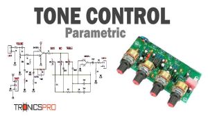
![Parametric Tone Control Circuit using LM4558 IC]()
Parametric Tone Control Circuit Diagram using LM4558 IC
![VU Meter Circuit Diagram One Transistor 6 LEDs]()
VU Meter Circuit Diagram One Transistor 6 LEDs
![120W Amplifier Circuit Diagram using 2SC5200 & 2SA1943 Apex Kelvin AX14]()
120W Amplifier Circuit Diagram using 2SC5200 & 2SA1943 Apex Kelvin AX14
![Top TDA2030 Amplifier Circuit Diagrams Tronicspro]()
Top TDA2030 Amplifier Circuit Diagrams Tronicspro
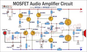
![MOSFET Amplifier Circuit using IRF530 & IRF9530]()
MOSFET Audio Amplifier Circuit Diagram using IRF530 & IRF9530


Actually this is a very good socket I have tried it out and it has work for several years in many cases but recently we are not able to do the same as because of the prevalence of contr feet electronic items in the market place many many items many many repair jobs have to be postpone and have to be neglected because of the arrival of non standard components which appear good on multimeter but when we put it on the replacement the blow up for no reason that I hope there is some mechanism, we will give some relief to technicians of whom many of them are even leaving the business due to this reason.