Introduction
A bass amplifier is an essential component for any musician or audio enthusiast looking to enhance their low-frequency sound experience. It helps in producing powerful, deep, and rich bass tones that add depth and definition to music. In this article, we will discuss a bass amplifier circuit diagram using popular transistors TIP3055, TIP2955, and the TDA2030 IC. These components offer a reliable and efficient solution for building a top-notch bass amplifier. We will also provide specifications for each of these components to help you better understand their capabilities and potential. So, without further ado, let’s dive into the details.
Specifications of TIP3055
- Maximum collector-emitter voltage (Vce): 60V
- Maximum collector current (Ic): 15A
- Maximum power dissipation (Pd): 115W
- Transition frequency (ft): 3MHz
- Package Type: TO-3
Specifications of TIP2955
- Maximum collector-emitter voltage (Vce): 60V
- Maximum collector current (Ic): 15A
- Maximum power dissipation (Pd): 90W
- Transition frequency (ft): 3MHz
- Package Type: TO-3
Specifications of TDA2030
- Supply Voltage (Vs): 6V to 36V
- Output Power: 14W (with 4Ω load) / 8W (with 8Ω load)
- Harmonic Distortion: 0.03% (typical)
- Signal-to-Noise Ratio: 100dB (typical)
- Package Type: Pentawatt V
Bass Amplifier Circuit using TIP3055 & TDA2030
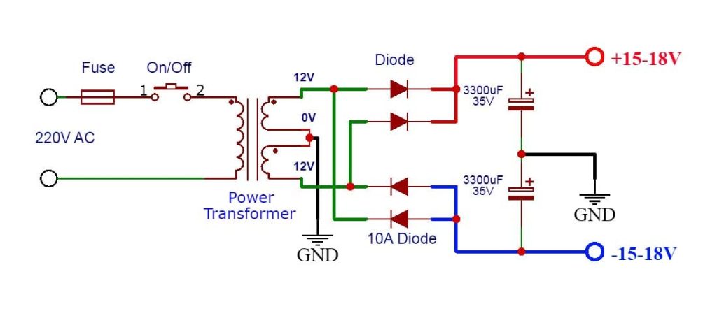
This project can be built using a few basic components. The circuit diagram of this project is shown below.
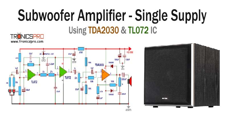
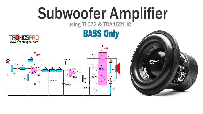
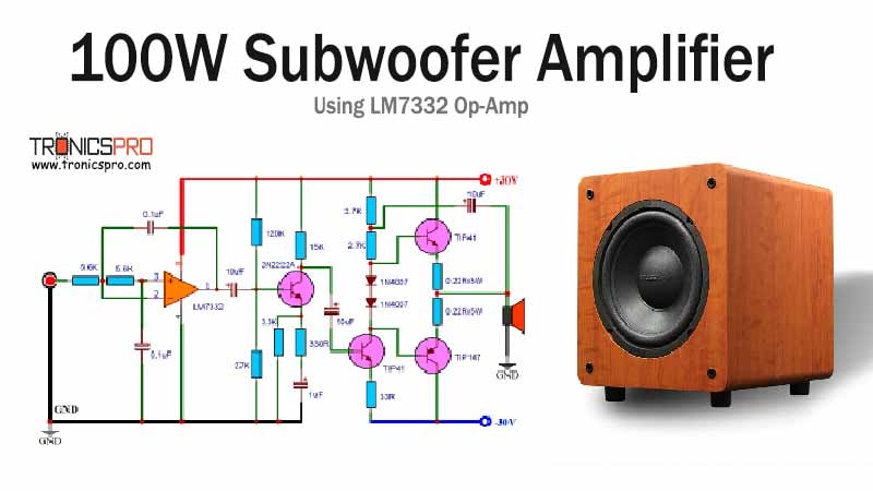
More Circuit Layouts



Components List of Bass Amplifier Circuit using TIP3055 & TDA2030
Following is the list of all components used in this project:
- TIP3055 Transistor x 1
- TIP2955 Transistor x 1
- TDA2030 IC x 1
- 56k Resister x 3
- 3.3k Resister x 1
- 1.5Ω Resister x 2
- 30k Resister x 1
- 1Ω/2W Resister x 1
- 47uF Capacitor x 1
- 10uF Capacitor x 1
- 470nF Capacitor x 1
- 220nF Capacitor x 3
- 2200uF Capacitor x 2
- 1N4001 Diode x 2
Explanation of Bass Amplifier Circuit using TIP3055 & TDA2030
The bass amplifier circuit we will discuss is straightforward, yet it delivers impressive performance. It consists of two transistors, TIP3055 and TIP2955, serving as the power amplifiers. These transistors are renowned for their high power handling capability, making them suitable for driving large speakers without any distortion or compromise in audio quality.
The TDA2030 is an integrated circuit (IC) used as the preamplifier in this circuit. This IC is widely used in audio amplifier applications due to its low harmonic distortion and high output power. Its ability to provide an exceptional signal-to-noise ratio ensures a clear and noise-free audio experience.
As shown in the diagram, the TDA2030 IC takes the input audio signal and amplifies it. This amplified signal then passes through the transistors TIP3055 and TIP2955, where it receives further power amplification. The output from the transistors is then delivered to the speaker for producing the desired bass tones.
Conclusion
Building your own bass amplifier can be an exciting and rewarding project, especially when using high-quality components like the TIP3055, TIP2955, and TDA2030. These components provide a solid foundation for a powerful and distortion-free bass amplifier circuit. The TIP3055 and TIP2955 transistors offer excellent power handling, ensuring that even the deepest bass tones are accurately reproduced without any compromise in audio quality. Furthermore, the TDA2030 IC serves as an efficient pre-amplifier to amplify the input audio signal, while its low harmonic distortion guarantees a clean and noise-free audio experience.
In conclusion, the bass amplifier circuit diagram using TIP3055, TIP2955, and TDA2030 is an ideal choice for those seeking to enhance their bass sound experience. By utilizing these components, you can build a reliable and efficient bass amplifier that delivers exceptional performance. Whether you are a musician or an audio enthusiast, this circuit will undoubtedly impress you with its deep, rich bass tones. So, roll up your sleeves, gather the components, and embark on your bass amplifier project today!
More projects, You may like:
- Video Transmitter DIY Homemade FM Radio Transmitter
- Adjustable Power Supply DIY Battery Charger
- 12V-220V 500 Watt inverter DIY Homemade
- MPPT Solar Charge Controller DIY Homemade
- DIY LA4440 bass amplifier homemade
For more project and circuit diagrams, you can go through the Schematics in the main menu where you can find many interesting projects and circuit diagrams like audio amplifier circuits, voltage booster circuit, and timer circuits etc. Feel free to check them out!


Thank you for visiting the article.


