Introduction
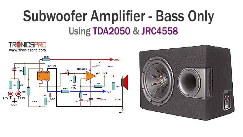
The TDA2050 Subwoofer Amplifier Circuit Diagram using JRC4558 IC is an excellent choice for audio enthusiasts who are looking to enhance their audio experience. This circuit diagram provides high-quality audio amplification, especially for subwoofers. By incorporating the powerful TDA2050 and reliable JRC4558 IC, this amplifier circuit delivers exceptional sound performance.
Specifications of TDA2050 IC:
- Output Power: 32 Watts
- Operating Voltage: 8 to 34 volts
- Total Harmonic Distortion: 0.05%
- Frequency Range: 20Hz to 20kHz
- THD + N Ratio: 0.1%
- Protection: Thermal Shutdown, Overload Protection
Specifications of JRC4558 IC:
- Minimum Operating Voltage: ±5V
- Maximum Operating Voltage: ±18V
- Input Voltage Range: ±12V
- Input Bias Current: 200nA
- High Voltage Gain: 100dB
- Low Noise Operation
TDA2050 Subwoofer Amplifier Circuit Diagram using JRC4558 IC
This project can be built using a few basic components. The circuit diagram of this project is shown below.
More Circuit Layouts


Components List of Subwoofer Amplifier Circuit using JRC4558 IC
Following is the list of all components used in this project:
- TDA2050 IC x 1
- JRC4558 IC x 1
- 33k Resister x 2
- 100k Resister x 2
- 22k Resister x 3
- 680R Resister x 3
- 2R2 Resister x 1
- 1uF Capacitor x 2
- 0.1uF Capacitor x 2
- 22uF Capacitor x 1
- 100nF Capacitor x 2
- 0.47uF Capacitor x 1
- 220uF Capacitor x 2
Explanation of Subwoofer Amplifier Circuit using JRC4558 IC
The TDA2050 is a popular and widely used audio amplifier integrated circuit. It operates on a wide range of power supply voltages, making it versatile for various audio setups. Its 32W output power capability makes it suitable for subwoofer applications. Additionally, this IC offers excellent protection features such as thermal shutdown and overload protection, ensuring long-term durability.
On the other hand, the JRC4558 IC is an operational amplifier that plays a crucial role in the amplification process. It is known for its low noise operation and high voltage gain, making it an ideal choice for audio amplification applications. With its ability to provide a crisp and clear audio output, the JRC4558 IC compliments the TDA2050 perfectly.
Conclusion
In conclusion, the Subwoofer Amplifier Circuit Diagram using the JRC4558 & TDA2050 IC is an excellent choice for enhancing the audio experience with its powerful and efficient performance. The integration of the TDA2050 and JRC4558 ICs ensures optimal sound quality, reliability, and easy implementation. The circuit diagram provides a clear understanding of the connections, making it convenient for both beginners and experienced electronics enthusiasts. Whether for home entertainment systems or professional audio setups, this amplifier circuit offers superior bass reproduction and precise control, making it an ideal solution for any subwoofer application.
More projects, You may like:
- Video Transmitter DIY Homemade FM Radio Transmitter
- Adjustable Power Supply DIY Battery Charger
- 12V-220V 500 Watt inverter DIY Homemade
- 12V-220V H-Bridge Inverter DIY Homemade
- MPPT Solar Charge Controller DIY Homemade
- 18650 battery bank free charge protection module
- D718 B688 Bass Amplifier Homemade DIY
- C5200 Bass Amplifier DIY Homemade with Volume
- DIY LA4440 bass amplifier homemade
- C5200 A1943 TDA2030 Amplifier DIY Homemade
For more project and circuit diagrams, you can go through the Schematics in the main menu where you can find many interesting projects and circuit diagrams like audio amplifier circuits, voltage booster circuit, battery charger circuit and timer circuits etc., which are all beginner circuit projects. Feel free to check them out!


Thank you for visiting the article.


