


Introduction
The demand for high-quality sound reproduction has led to the development of powerful audio amplifiers. Among them, the 100W audio amplifier circuit diagram stands out, delivering an exceptional listening experience. We will explain the working principles and features of this amplifier, which utilizes 4 x 2N3055 transistors in the output section, and 2N3904 and 2N3906 transistors in the audio section. With its efficient design and use of high-ranking components, this amplifier promises to be a reliable choice..
An audio amplifier is an electronic device that amplifies low-power audio signals to a level suitable for driving speakers. It is an essential component in audio systems, ranging from personal electronic devices to home theater setups. In this article, we will discuss a 100W audio amplifier circuit diagram using the popular 2N3055 transistor. This circuit offers a powerful and efficient solution for audio amplification, making it a popular choice among audio enthusiasts and professionals alike.
>
Circuit Diagram of 100W Audio Amplifier Circuit
This project can be designed using a few basic components. The circuit diagram of this project is shown below.

More Circuit Layouts


Components List of 100W Audio Amplifier Circuit
Following is the list of all components used in this project:
- 2N3055 Transistor x 4
- 2N3904 Transistor x 1
- 2N3906 Transistor x 1
- 0.33 ohm 5W Resister x 4
- 100 ohm Resister x 1
- 15 ohm Resister x 1
- 47 ohm Resister x 3
- 2.2k Resister x 2
- 470 ohm Resister x 1
- 1uF Capacitor x 1
- 4700uF Resister x 1
- 1N4001 Diode x 2
- Power Supply 12-24V
- Speaker 4 ohm
Explanation
Understanding the 100W Audio Amplifier Circuit
The 100W audio amplifier circuit diagram features a well-optimized configuration for delivering powerful audio output. It comprises two main sections: the audio section and the output section.
A. Audio Section:
The audio section of this amplifier employs 2N3904 NPN and 2N3906 PNP transistors, which are renowned for their small size and high performance. These transistors are designed to deliver low distortion and excellent response across the audio frequency range. Their compact size also makes them ideally suited for compact audio amplifier designs.
B. Output Section:
For the output section, 4 x 2N3055 power transistors are configured in a complimentary push-pull arrangement. This configuration ensures efficient power handling and reduced distortion. The 2N3055 transistors are popular for their ability to handle high voltages and currents, making them well-suited for high-powered audio applications.
Working Principles of the 100W Audio Amplifier Circuit
The 100W audio amplifier circuit diagram operates on the principles of amplification and power handling. Here’s a simplified explanation of how it works:
- Audio Section: The audio input signal is first amplified by the 2N3904 and 2N3906 transistors in the audio section. The 2N3904 transistor, acting as an NPN amplifier, amplifies the positive half of the audio signal, while the 2N3906, acting as a PNP amplifier, amplifies the negative half. This ensures a balanced amplification of the audio signal, reducing distortion.
- Output Section: The amplified audio signal is then fed into the output section, where the 4 x 2N3055 transistors serve as the power amplifiers. These transistors, arranged in a push-pull configuration, amplify the signal to a higher power level suitable for driving speakers. The push-pull configuration eliminates the DC component and greatly reduces distortion. The resulting amplified audio signal is then sent to the speakers, producing high-quality sound reproduction.
Specifications of 2N3055 Transistor:
The 2N3055 is a silicon NPN power transistor widely used in audio amplifier circuits due to its high power dissipation capacity and low collector-emitter saturation voltage. It is a versatile power transistor with impressive specifications. Here are some key specifications that make it an ideal choice for the output section of the 100W audio amplifier circuit diagram:
- Maximum Collector-Emitter Voltage (VCEO): 60V
- Maximum Collector Current (IC): 15A
- Maximum Power Dissipation (Pd): 115W
- Maximum Transition Frequency (ft): 2.5 MHz
- DC Current Gain (hFE): 20 to 70 (typical)
These specifications highlight the 2N3055 transistor’s ability to handle high voltages and currents, making it suitable for delivering the power required for the audio output section.
Conclusion
The 100W audio amplifier circuit diagram offers a powerful solution for audio enthusiasts. With its efficient design, low distortion, and robust power handling capabilities, this amplifier ensures a superior listening experience. Whether used in home audio systems, musical instruments, or professional sound setups, the 100W audio amplifier circuit is a reliable choice. Its high-ranking components and optimized configuration make it an appealing option for those seeking exceptional audio performance.
Its circuit design offers high power dissipation capability and low saturation voltage. This results in a high-quality audio output with minimal distortion. The circuit’s working principle involves a biasing network, coupling network, and frequency response stabilization components. All these elements work together to ensure stable and distortion-free amplification.
In conclusion, the 100W audio amplifier using the 2N3055 transistor is a reliable and efficient solution for audio amplification needs. Whether you are an audio enthusiast looking to build your own amplifier or a professional seeking a powerful audio solution, this circuit provides an excellent option. With its straightforward design and the use of high-quality components, this circuit promises to deliver high-quality audio output for your listening pleasure.
More projects, You may like:
- Video Transmitter DIY Homemade FM Radio Transmitter
- Adjustable Power Supply DIY Battery Charger
- 12V-220V 500 Watt inverter DIY Homemade
- 12V-220V H-Bridge Inverter DIY Homemade
- MPPT Solar Charge Controller DIY Homemade
- 18650 battery bank free charge protection module
- D718 B688 Bass Amplifier Homemade DIY
- C5200 Bass Amplifier DIY Homemade with Volume
- DIY LA4440 bass amplifier homemade
- C5200 A1943 TDA2030 Amplifier DIY Homemade
For more project and circuit diagrams, you can go through the Schematics in the main menu where you can find many interesting projects and circuit diagrams like audio amplifier circuits, voltage booster circuit, battery charger circuit and timer circuits etc., which are all beginner circuit projects. Feel free to check them out!


Thank you for visiting the article.
You may also like:
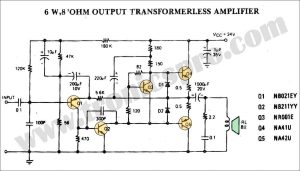
![Transformerless Power Amplifier Circuit Diagram]()
Transformerless Power Amplifier Circuit Diagram
![One Transistor Audio Mixer Circuit Diagram]()
One-Transistor Audio Mixer Circuit Diagram
![Audio Amplifier Circuit Diagram using STK4141 IC]()
50W Stereo Power Amplifier Circuit Diagram STK4141
![500W c5200 a1943 Power Amplifier Circuit Diagram]()
500W Power Amplifier Circuit using c5200 a1943
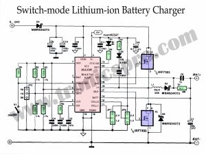
![Lithium-ion Battery Charger Switch-mode Circuit Diagram]()
Lithium-ion Battery Charger Switch-mode
![100W 2N3055 Bridge Amplifier Circuit Diagram]()
100W 2N3055 Bridge Amplifier Circuit Diagram
![100W Audio Amplifier Circuit Diagram using 2N3055 & MJ15004]()
100W Audio Amplifier Circuit Diagram using 2N3055 & MJ15004
![TDA2030 Subwoofer Amplificer Circuit with 4558 IC]()
TDA2030 Subwoofer Amplificer Circuit Diagram with 4558 IC


NO WORK !!!!!!!!!! 2n3906 wrong position. 12-24v 100w no way.
In case I want to add a volume control to this amplifier, what would be the best way to do it?