


Introduction
A 500W power amplifier is a device widely used in the audio industry to enhance the audio signal and produce high-quality sound output. This article presents a circuit diagram for a 500W power amplifier circuit that utilizes advanced components such as IRFP240 and IRFP9240 MOSFETs in the output stage, MJE340 and MJE350 transistors in the driver section, and 2SA970 transistors in the preamplifier section. This circuit diagram ensures optimal performance and superior sound quality, making it an ideal choice for audio enthusiasts and professionals.
Specifications of Components:
Here are the specifications of the components used in the circuit diagram:
- IRFP240 MOSFET:
- Power Handling Capacity: 200W
- Drain-Source Voltage: 200V
- Gate-Source Voltage: ±20V
- Drain Current: 18A
- IRFP9240 MOSFET:
- Power Handling Capacity: 200W
- Drain-Source Voltage: -200V
- Gate-Source Voltage: ±20V
- Drain Current: 12A
- MJE340 Transistor:
- Collector-Base Voltage: 300V
- Collector Current: 500mA
- Power Dissipation: 1.5W
- Transition Frequency: 100MHz
- MJE350 Transistor:
- Collector-Base Voltage: 300V
- Collector Current: 500mA
- Power Dissipation: 1.5W
- Transition Frequency: 100MHz
- 2SA970 Transistor:
- Collector-Base Voltage: -120V
- Collector Current: -150mA
- Power Dissipation: 200mW
- Transition Frequency: 50MHz
500W Amplifier Circuit Diagram using IRFP240 & IRFP9240
This project can be built using a few basic components. The circuit diagram of this project is shown below.


Caution: Website contains information on high voltage circuits. Proceed at your own risk, ensuring proper knowledge and precautionary measures to prevent electric shock or injury.
More Circuit Layouts


Components List of 500W Amplifier Circuit using IRFP240 & IRFP9240
Following is the list of all components used in this project:
- IRFP240 MOSFET x 4
- IRFP9240 MOSFET x 4
- MJE340 Transistor x 2
- MJE350 Transistor x 1
- 2SA970 Transistor x 2
Explanation of 500W Amplifier Circuit using IRFP240 & IRFP9240
The 500W power amplifier circuit diagram consists of different sections that work together to amplify the audio signal. The key elements of this circuit are the IRFP240 and IRFP9240 MOSFETs in the output stage. These MOSFETs provide high power handling capabilities and low distortion, ensuring clean and crisp sound output.
In the driver section, the MJE340 and MJE350 transistors play a vital role. These transistors amplify the signal from the preamplifier section and provide sufficient drive to the MOSFETs in the output stage. The MJE340 and MJE350 transistors are known for their excellent gain characteristics and low collector-emitter saturation voltage, making them ideal for the driver section.
Furthermore, the 2SA970 transistors in the preamplifier section amplify the incoming audio signal to a suitable level for further processing. These transistors offer low noise and distortion, ensuring the original audio signal is preserved and amplified accurately.
The combination of these advanced components in the circuit diagram ensures a powerful, distortion-free, and high-quality sound output, making it a popular choice among audio enthusiasts and professionals.
Conclusion
In conclusion, the 500W power amplifier circuit diagram using IRFP240 and IRFP9240 presented in this article offers exceptional sound quality and high power handling capabilities. By utilizing advanced components such as IRFP240 and IRFP9240 MOSFETs in the output stage, MJE340 and MJE350 transistors in the driver section, and 2SA970 transistors in the preamplifier section, this circuit diagram ensures optimal performance and superior audio output. Whether for audio enthusiasts or professionals, this 500W power amplifier is an excellent choice, delivering powerful sound reproduction with minimal distortion.
More projects, You may like:
- Video Transmitter DIY Homemade FM Radio Transmitter
- Adjustable Power Supply DIY Battery Charger
- 12V-220V 500 Watt inverter DIY Homemade
- MPPT Solar Charge Controller DIY Homemade
- DIY LA4440 bass amplifier homemade
For more project and circuit diagrams, you can go through the Schematics in the main menu where you can find many interesting projects and circuit diagrams like audio amplifier circuits, voltage booster circuit, battery charger circuit and timer circuits etc., which are all beginner circuit projects. Feel free to check them out!

Thank you for visiting the article.
You may also like:
![30W Stereo Amplifier TDA7297]()
30W Stereo Amplifier TDA7297 DIY Circuit
![Fifth-Order Low-Pass Filter Circuit Diagram]()
Fifth-Order Low-Pass Filter Circuit Diagram
![100W Audio Amplifier Circuit using TIP3055]()
100W Audio Amplifier Circuit using TIP3055
![Stereo Tone Control Circuit Diagram using NE5532 IC]()
Stereo Tone Control Circuit Diagram using NE5532 IC
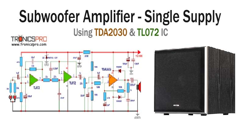
![Subwoofer Amplifier Circuit using TL072 & TDA1521 IC]()
Subwoofer Amplifier Circuit Diagram using TL072 & TDA1521 IC
![100W MOSFET Audio Amplifier Circuit Diagram using IRF530 & IRF9530]()
100W MOSFET Audio Amplifier Circuit Diagram using IRF530 & IRF9530
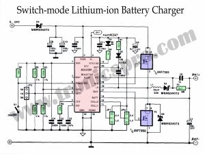
![Lithium-ion Battery Charger Switch-mode Circuit Diagram]()
Lithium-ion Battery Charger Switch-mode
![IR Intruder Alarm Amplifier Circuit Diagram]()
IR Intruder Alarm Circuit Diagram (Infrared)


Boa noite meu mestre, eu sou um antigo estudante de eletrônica , quando eu deparo com diferente plataforma moderna, e diferente,eu faço de tudo pra conhecer , meus parabéns guerreiro é muito importante pra nós estudante primeiro conhecer os diagrama e elogialo e as minhas satisfação é muito especial , nota 1000 e parabéns pô tudo já conquistado muito obrigado pela plataforma apresentada ok NINIL agradece felicidades ao seu negócio mano irmãos ,,,