Introduction

In the world of electronics, preamplifiers play a vital role in enhancing the weak signals from various audio sources or sensors before they are fed into the main amplifiers. A preamplifier circuit diagram that promises low-noise performance is a sought-after DIY project among electronics enthusiasts. In this article, we will explore the construction of such a preamp circuit and discuss the specifications of key components like the 2N3906 transistor and the 2N3819 MOSFET.
Preamplifier Circuit Diagram Low-Noise
This project can be built using a few basic components. The circuit diagram of this project is shown below.


More Circuit Layouts


Components List of Preamplifier Circuit Diagram Low-Noise
Following is the list of all components used in this project:
- 2N3906 Transistor PNP x 1
- 2N3819 Mosfet x 1
- 1k Resister x 2
- 2.2k Resister x 2
- 1M Resister x 1
- 10k Resister x 1
- 82 Ohms Resister x 1
- 10uF Capacitor x 1
- 220uF Capacitor x 1
- 0.47uF Capacitor x 1
- 12V to 30V Power Supply
Explanation of Preamplifier Circuit Diagram Low-Noise
In previous tutorials, we made 800W Amplifier using C5200 A1943, Subwoofer Amplifier 100W using LM7332 and 150W Audio Amplifier Circuit Diagram TIP3055. But in this tutorial, we will design a Preamplifier Circuit Diagram Low-Noise.
To begin with, let’s dive into the circuit diagram of a preamplifier that boasts low noise characteristics. This do-it-yourself (DIY) project allows electronics enthusiasts to build a high-quality preamplifier from scratch, ensuring optimal sound quality.
The heart of the circuit lies in two important components – the 2N3906 transistor and the 2N3819 MOSFET. First, let’s take a closer look at the specifications of these components.
Specifications:
- 2N3906 Transistor: This 2N3906 PNP bipolar transistor offers excellent low-noise characteristics and is widely used in audio amplifier circuits. It has a maximum collector current rating of 200mA and a power dissipation capability of 625mW. The transistor also offers a high current gain (hFE) in the range of 100-300, making it suitable for low-noise preamplifier applications.
- 2N3819 MOSFET: As a broadly used N-channel enhancement-mode MOSFET, the 2N3819 is renowned for its low noise performance and high input impedance. It exhibits a maximum drain current (IDSS) of 20mA and operates within a voltage range of 25V. The input capacitance (Ciss) and output capacitance (Coss) of this MOSFET are typically around 8pF, minimizing any unwanted signal degradation.
Conclusion
Building a preamplifier circuit diagram with low-noise amplification capabilities can greatly enhance the audio experience. By utilizing the aforementioned 2N3906 transistor and 2N3819 MOSFET, the preamplifier circuit diagram low-noise can achieve superior noise performance. This DIY project empowers electronics enthusiasts to construct their own high-quality preamplifier, catering to their specific needs and preferences. This article aims to provide readers with valuable information, allowing them to successfully undertake this DIY venture. Happy constructing!
More projects, You may like:
- Video Transmitter DIY Homemade FM Radio Transmitter
- Adjustable Power Supply DIY Battery Charger
- 12V-220V 500 Watt inverter DIY Homemade
- 12V-220V H-Bridge Inverter DIY Homemade
- MPPT Solar Charge Controller DIY Homemade
- 18650 battery bank free charge protection module
- D718 B688 Bass Amplifier Homemade DIY
- C5200 Bass Amplifier DIY Homemade with Volume
- DIY LA4440 bass amplifier homemade
- C5200 A1943 TDA2030 Amplifier DIY Homemade
For more project and circuit diagrams, you can go through the Schematics in the main menu where you can find many interesting projects and circuit diagrams like audio amplifier circuits, voltage booster circuit, battery charger circuit and timer circuits etc., which are all beginner circuit projects. Feel free to check them out!
Thank you for visiting the article.
You may also like:
![240W Power Amplifier Circuit Diagram using PNP Transistors]()
240W Power Amplifier Circuit Diagram using PNP Transistors
![LA4440 Stereo Amplifier Circuit Diagram]()
LA4440 Stereo Amplifier Circuit Diagram
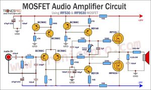
![MOSFET Amplifier Circuit using IRF530 & IRF9530]()
MOSFET Audio Amplifier Circuit Diagram using IRF530 & IRF9530
![Phono Amplifier Circuit Diagrams - TRONICSpro]()
Phono Amplifier Circuit Diagrams - TRONICSpro
![IR Receiver Circuit Diagram]()
IR Receiver Circuit Diagram (Infrared)
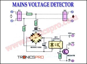
![Mains Voltage Detector Circuit Diagram]()
Mains Voltage Detector Circuit Diagram
![4-bit Analog-to-Digital Converter Circuit]()
4-bit Analog-to-Digital Converter Circuit
![28V High Current Power Supply Circuit Diagram]()
28V High Current Power Supply Circuit Diagram