
In this article, we will discuss a bass preamplifier circuit diagram for subwoofer that utilizes BC546 and BC556 transistors which will help to enhance the bass frequencies, allowing for a richer and more immersive audio experience.

In this article, we will discuss a bass preamplifier circuit diagram for subwoofer that utilizes BC546 and BC556 transistors which will help to enhance the bass frequencies, allowing for a richer and more immersive audio experience.

In this article, we will explore three input Microphone Preamplifier Circuit Diagram using LM348 single IC. The LM348 is a versatile operational amplifier (Op-Amp) that provides a high-quality, low-noise amplification solution for various audio application

This DIY project empowers electronics enthusiasts to construct their own high-quality preamplifier circuit diagram with very low-noise, catering to their specific needs and preferences. This article aims to provide readers with valuable information, allowing them to successfully undertake this DIY venture.

The preamplifier circuit diagram using the BC140 discussed in this article demonstrates a simple yet effective configuration utilizing the BC140 transistor for amplifying weak audio signals. With its low saturation voltage, high current gain, and wide frequency response, the BC140 transistor ensures high-quality audio amplification for various applications.

The audio preamplifier circuit diagram using the 2N3903 transistor is a reliable and effective solution for amplifying weak audio signals. The circuit diagram, consisting of the 2N3903 transistor, resistors, capacitors, and audio input and output, provides excellent gain and frequency response characteristics.

This article will guide you about Preamplifier Circuit Diagram using TL072 IC through the specification of the TL072 IC, and discuss the advantages it offers.

In this article, we will discuss the design and implementation of a subwoofer filter circuit low pass using the TL072 operational amplifier, which is known for its excellent audio performance.

A low pass filter circuit is an essential component in audio systems, especially when it comes to subwoofer preamplifiers. It effectively filters out high-frequency signals, allowing only low-frequency signals to pass through, thus producing a clearer and more defined bass output.

Following the the circuit diagram of Stereo Preamplifier Circuit LM382 which is a general purpose amplifier and can be used with microphone or phono.
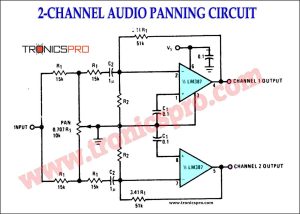
A 2-channel audio panning circuit using the LM387 IC is a simple and effective way to add panning effects to a stereo audio signal. With a few simple adjustments to the circuit, the signal can be panned left or right, and the balance control can be used to fine-tune the overall mix.

 Variable Power Supply 0-30V_10A Circuit Diagram
 C5200 A1943 TDA2030 Amplifier DIY Homemade
 DIY LA4440 bass amplifier homemade
 Bass Tone Control Circuit Diagram – TRONICSpro
 2N3055 stereo amplifier homemade bluetooth diy
 500W Power Amplifier Circuit using c5200 a1943
 DIY bass treble volume homemade Tone Control
 Subwoofer Amplifier Circuit Diagram using TDA2030
 KSP92 Pinout, Equivalent Application Datasheet
 KSP44 Pinout, Equivalent Application Datasheet
 MPSA92 Pinout, Equivalent Application Datasheet
 MPSA42 Pinout, Equivalent Application Datasheet
 PN200 Pinout, Equivalent Application Datasheet
 PN100 Pinout, Equivalent Application Datasheet
 MJE802 Pinout, Equivalent Application Datasheet
 MJE800 Pinout, Equivalent Application Datasheet