

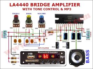
The C5200 A1943 JRC4558 amplifier with tone control is a popular DIY homemade project for audio enthusiasts. It combines the power and efficiency of the C5200 and A1943 transistors with the superior sound quality of the JRC4558 operational amplifier. This amplifier provides a clean and powerful audio output while offering the flexibility of tone control for an enhanced listening experience. Building this amplifier from scratch allows individuals to customize the design and components to suit their preferences.
In the following video I showed, how to make a powerful C5200 A1943 Mono Amplifier with jrc4558 ic and heavy bass, treble and volume controllers (tone control). The high quality circuit uses minimum components with a low cost and ideal for beginners and students.
The following video was sponsored by PCBGOGO, a most experienced pcb manufacturer in China. They provide high quality manufacturing of pcb and pcb assemblies. Also they have 24 hours online customer service to handle the engineer’s questions or follow up the orders. Also they provide $50 coupon for new registrant.

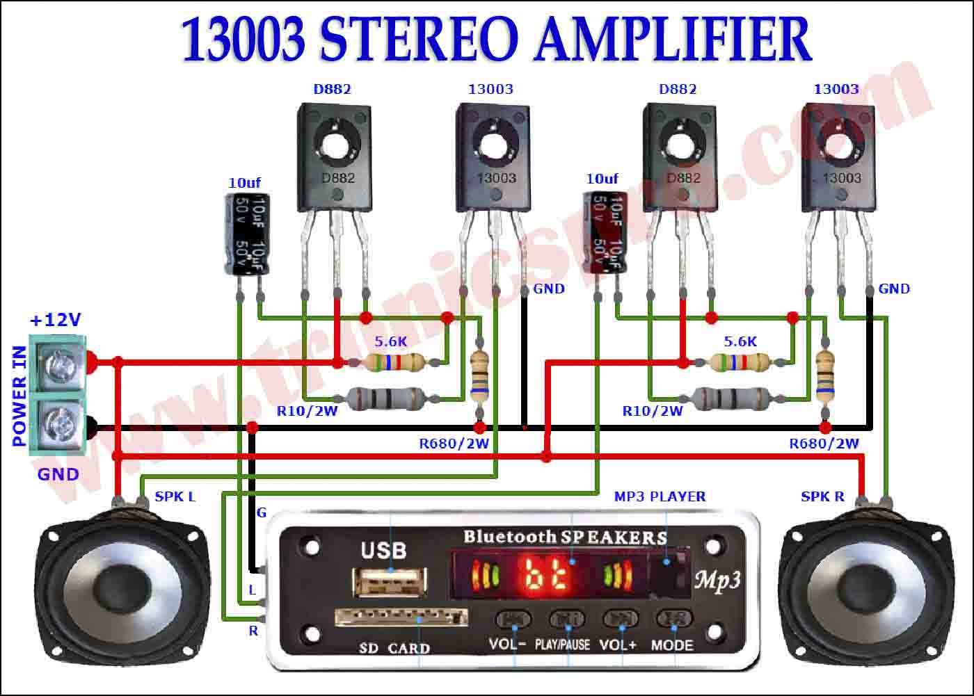
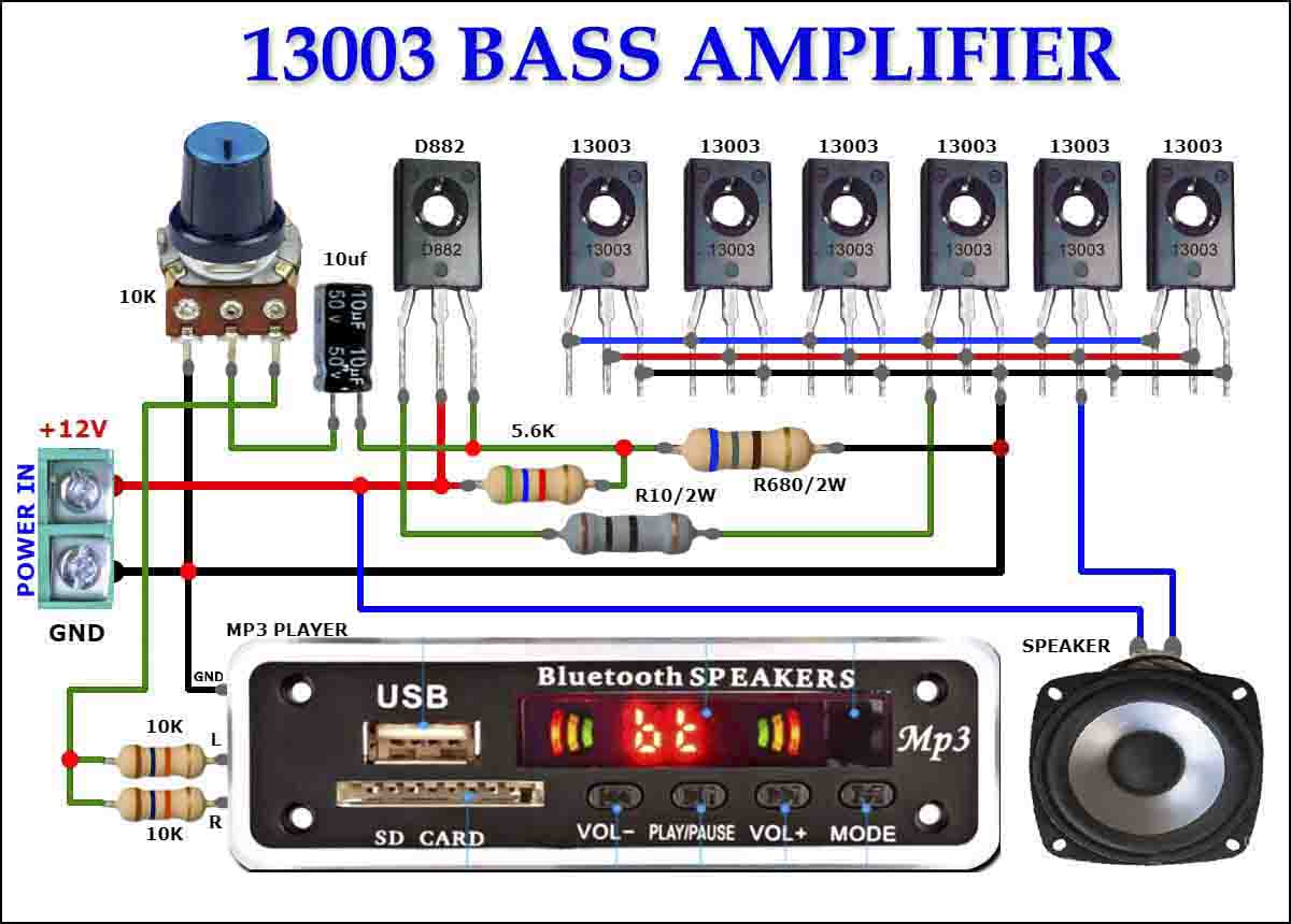
Circuit Diagram
This is the circuit diagram of C5200 & A1943 Mono Amplifier using jrc4558 ic including bass, treble and volume controllers. Click on the image to open it in a light box then click the “Download” button to download the circuit diagram into your computer or mobile.


List on components used in C5200 A1943 JRC4558 amplifier
- 2SC5200 transistor x 2
- 2SA1943 transistor x 2
- JRC4558 IC x 1
- 4700uf 50v capacitor x 1
- 47uf capacitor x 1
- 10uf capacitor x 1
- 0.47 ohms 5 watts resister x 2
- 100 ohms 2 watts resister x 1
- 10k resister x 2
- 47k resister x 1
- 100k resister x 1
- 1k resister x 1
- 50k potentiometer x 1
- Power supply 18v dc
- Speaker 4 ohms
Development images
used in C5200 A1943 JRC4558 amplifier
List of basic components:
Here are the basic components in the following two images which will be used in the said project. Complete list of components is provided above in the ‘Components List‘ section of this article.


Installing components:
Take one large and thick heat sink for two main transistors C5200 NPN and A1943 PNP for proper heat dissipation. Use mica underneath the both transistors which will prevent them touching with the heat sink. Don’t forget to check the continuity with multi meter from collector to heat sink. It is mandatory because the center pins (collectors) of both the transistors will run opposite voltage which will cause short circuit. Well tighten the transistors with heat sink.
Take two pieces of 0.47 ohms 5 watts resisters and solder each of them with pin-3 (emitters) of each transistors. And then join the other legs of both resisters each other, as shown in the following image.

Soldering components:
Now take a small piece of naked wire and solder its both end to pin-1 (base) of both the transistors. Like this way you will connect both base of of both transistor together. Now take JRC458 IC and solder its pin-1 with the naked wire piece as shown.

Take one 100 ohms resister of 2 watts and solder its one leg to pin-8 of JRC4558 IC and the other leg solder with the center pin-2 (collector) of C5200 transistor.

Now take a 10k resister and solder its one leg with pin.8 and the other leg with pin.3 of JRC4558 IC.

Take one piece of small wire and solder its one end with center pin.2 of A1943 transistor and the other end solder with pin.4 of JRC458 IC. Also take one 47uf electrolytic capacitor and solder its positive pin to pin.3 and negative pin to pin.4 (GND) of JRC4558 IC.

Now take a 10k resister and solder it with pin.3 and pin.4 of JRC458 IC.

Now take one 10uf electrolytic capacitor and solder its positive leg to pin.2 of JRC4558 IC.

Take one 100k resister and solder its one leg with negative leg of 10uf capacitor and the other leg to pin.4 (GND) of JRC4558 IC.

Use now a 1k resister and solder its one leg with negative leg of 10uf capacitor where 100k resister was joined earlier.

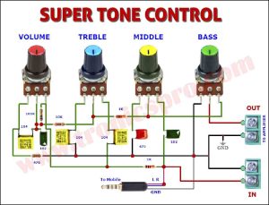
Setting tone controller:
I used here a tone control circuit which I will not explain here. This project is already available at this site. If you want to visit, click this link of Tone Controller for further detail.

Connect and solder the other end of 1k resister with center pin of volume controller of the tone control.

External connections:
Now take 3.5mm mobile jack and solder its GND of pin.3 GND of volume controller. And other two wires solder with pin.1 of bass controller.

Take one power supply socket and solder its red positive wire to center pin.2 (collector) of C5200 NPN transistor. And also solder the black negative wire with center pin.2 (collector) of A1943 PNP transistor. If you don’t want to use this socket, you can solder the power supply connections directly.

Take two piece of wires for speaker output. Solder one black to center pin.2 of A1943 PNP transistor and the other red solder with the negative leg of 2200uf electrolytic capacitor.

In the below image I am showing the single voltage power supply of 12 volts 1.25 amps, which will be used to drive the said amplifier for demonstration.

Following image shows the amplifier in action. I used two 4 ohms speakers in parallel. If you want to see it live then watch video at the bottom of this article.

Conclusion:
In conclusion, the C5200 A1943 JRC4558 amplifier with tone control is a fantastic DIY homemade project for audio enthusiasts. Its a combination of powerful C5200 and A1943 transistors and the high-quality JRC4558 operational amplifier ensures a clean and powerful audio output. Additionally, the inclusion of tone control allows for customization of the sound to suit individual preferences. By building this amplifier from scratch, individuals can not only experience the joy of DIY but also have the freedom to personalize the design and choose the components for their specific needs. Whether it’s for home audio or a DIY audio project, this amplifier provides a reliable and superior audio performance.
Thanks for watching & visiting the site. Please share it with your friends. Thank you.
You may also like:
![TDA2030 DIY Powerful Amplifier with Volume Bass Treble]()
TDA2030 DIY Powerful Amplifier with Volume Bass Treble
![DIY Powerful 2SC5200 Amplifier Homemade Ultra Bass]()
DIY Powerful 2SC5200 Amplifier Homemade Ultra Bass
![C5200 Stereo Bass Amplifier DIY Volume Bass Treble]()
C5200 Stereo Bass Amplifier DIY Volume Bass Treble
![D718 amplifier DIY homemade]()
DIY homemade D718 amplifier ultra bass
![DIY D718 D882 amplifier homemade DIY]()
DIY D718 D882 amplifier homemade DIY
![C5200 DIY Stereo Amplifier Thumbnail]()
C5200 DIY Stereo Amplifier Powerful Ultra Bass
![c5200 a1943 amplifier diy homemade]()
C5200 A1943 amplifier DIY homemade
![C5200 bass amplifier DIY homemade]()
C5200 bass amplifier DIY homemade


Muy agradecido por tu colaboración para desarrollar más fácilmente y resolver problemas sin diagrama
Muchas gracias por visitar el sitio y sus comentarios.
muy bueno, me gusta, esta muy claro y muy facil de harmar…gracias
Muchas gracias por los comentarios positivos.
Thanks for this video it’s very helpful
Thank you.
Thanks.work perfect and cool