

Introduction

In the world of audio amplifiers, power and quality go hand in hand. To achieve the perfect balance, many DIY enthusiasts have turned to building their own amplifiers. One such popular choice is the 200W MOSFET Amplifier Circuit. This circuit utilizes two pairs of ECX10N16 and ECX10P16 MOSFETs in the output section, two pairs of MJE340 and MJE350 transistors in the driver section, and two pairs of BC556 transistors in the preamplifier section. Additionally, an overload protection circuit is incorporated, featuring two BC556 transistors.
ECX10N16 and ECX10P16 MOSFETs:
The ECX10N16 and ECX10P16 MOSFETs are the heart of this amplifier circuit. These MOSFETs offer excellent power handling capabilities and low distortion, making them ideal for high-performance audio amplifiers. The ECX10N16 is an N-channel MOSFET, while the ECX10P16 is a complementary P-channel MOSFET. This complementary pair ensures the balanced amplification of both the positive and negative halves of the audio signal, resulting in enhanced audio fidelity.
Specifications of ECX10N16 MOSFET:
- Drain-Source Voltage (VDS): 160V
- Continuous Drain Current (ID): 10A
- Power Dissipation (PD): 100W
- Gate-Source Voltage (VGS): ±20V
- Total Harmonic Distortion (THD): <0.1% (at 1kHz, 10W)
- Input Capacitance (Ciss): 680pF
- Output Capacitance (Coss): 180pF
- Reverse Transfer Capacitance (Crss): 50pF
Specifications of ECX10P16 MOSFET:
- Drain-Source Voltage (VDS): -160V
- Continuous Drain Current (ID): -10A
- Power Dissipation (PD): 100W
- Gate-Source Voltage (VGS): ±20V
- Total Harmonic Distortion (THD): <0.1% (at 1kHz, 10W)
- Input Capacitance (Ciss): 780pF
- Output Capacitance (Coss): 220pF
- Reverse Transfer Capacitance (Crss): 65pF
200W Mosfet Amplifier Circuit Diagram
This project can be built using a few basic components. The circuit diagram of this project is shown below.


Caution: Website contains information on high voltage circuits. Proceed at your own risk, ensuring proper knowledge and precautionary measures to prevent electric shock or injury.
More Circuit Layouts


Components List of 200W Mosfet Amplifier Circuit Diagram
Following is the list of all components used in this project:
- ECX10N16 MOSFET x 2 (Upper Mosfets)
- ECX10P16 MOSFET x 2 (Lower Mosfets) –> Not mentioned in circuit diagram.
- MJE340 Transistor x 2
- MJE350 Transistor x 2
- BC556 Transistor x 6
- 1N4002 Diode x 2
- 1N914 Diode x 2
- 12V/.5W Zener Diode x 2
- ±67V Power Supply
Explanation of 200W Mosfet Amplifier Circuit Diagram
Driver and Preamplifier Sections:
To ensure efficient driving of the output MOSFETs, the amplifier circuit employs two pairs of MJE340 and MJE350 transistors in the driver section. These transistors act as buffers, providing the necessary current amplification and voltage gain to properly drive the MOSFETs.
In the preamplifier section, two pairs of BC556 transistors are utilized. These transistors are known for their low noise and high gain characteristics, ensuring a clean and amplified audio signal is delivered to the driver stage.
Overload Protection Circuit:
To safeguard both the amplifier circuit and connected audio equipment from potential damage due to excessive input signal or short circuits, an overload protection circuit is implemented using two BC556 transistors. These transistors act as current limiters, detecting any abnormal signals and limiting the current flow accordingly.
Conclusion
The 200W MOSFET amplifier circuit utilizing ECX10N16 and ECX10P16 MOSFETs, MJE340 and MJE350 transistors, and BC556 transistors offers a powerful and high-fidelity audio amplification solution for DIY enthusiasts. With the incorporation of an overload protection circuit, this amplifier ensures reliable performance and safeguards against potential damages. Whether you are a seasoned audio enthusiast or a beginner in the world of DIY electronics, this amplifier circuit is sure to impress with its outstanding specifications and capabilities.
More projects, You may like:
- Video Transmitter DIY Homemade FM Radio Transmitter
- Adjustable Power Supply DIY Battery Charger
- 12V-220V H-Bridge Inverter DIY Homemade
- MPPT Solar Charge Controller DIY Homemade
For more project and circuit diagrams, you can go through the Schematics in the main menu where you can find many interesting projects and circuit diagrams like audio amplifier circuits, voltage booster circuit, and timer circuits etc. Feel free to check them out!

Thank you for visiting the article.
You may also like:
![Low Pass Filter Circuit Subwoofer Preamplifier]()
Low Pass Filter Circuit 4558 Subwoofer Preamplifier
![Celsius Thermometer Circuit Diagram]()
Celsius Thermometer Circuit Diagram
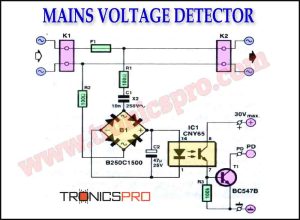
![Mains Voltage Detector Circuit Diagram]()
Mains Voltage Detector Circuit Diagram
![Build Your Own Stereo Amplifier with TDA1552 DIY]()
Build Your Own Stereo Amplifier with TDA1552 DIY
![300W OCL Power Amplifier Circuit using 2N3055 & MJ2955]()
300W OCL Power Amplifier Circuit Diagram using 2N3055 & MJ2955
![260W Power Amplifier Circuit Diagram using TIP140]()
260W Power Amplifier Circuit Diagram using TIP140 & TIP145 Transistors
![Power Amplifier Circuit using D1047 & B817 - ROTEL RA840B]()
Power Amplifier Circuit Diagram using D1047 & B817 - ROTEL RA840B
![Non-Inverting AC Power Amplifier Circuit Diagram]()
Non-Inverting AC Power Amplifier Circuit Diagram


can you send me a pcb file
In reviewing and transcribing your schematic, I noticed that one of the components marked BC556 may be labeled incorrectly or is drawn incorrectly. This is the third component from the left along the top of the diagram. Is it possible this is actually a BC557?
Lastly, is there a complete BOM of all the components used that would include resistors, capacitors, etc., and the wattage or voltage requirements?
You are right! bc556 is a PNP while this one is NPN. It’s a printing mistake.
And sorry for BOM, I don’t have.