Introduction
An inverting unity gain amplifier LM1877 circuit diagram using the LM1877 IC is a simple and effective way to amplify audio signals. This circuit is widely used in audio amplifiers, speakers, and headphones.
The LM1877 is a low-power audio amplifier that delivers high-quality sound reproduction. It is a dual-channel amplifier that can deliver up to 2 watts of power per channel. The LM1877 is designed to operate from a single power supply and can be configured as a stereo amplifier or a monaural amplifier.
The inverting unity gain amplifier circuit diagram using the LM1877 IC is simple and easy to construct. The circuit consists of a few components, including the LM1877 IC, a few resistors, capacitors, and a power supply. The circuit diagram is shown below:
Circuit Diagram
of Inverting Unity Gain Amplifier

More Circuit Layouts


The LM1877 IC is the heart of the circuit. It is a dual-channel audio amplifier that is designed to operate with a minimum number of external components. The LM1877 IC has a built-in gain control, which makes it suitable for use in audio applications.
Working Explanation
of Inverting Unity Gain Amplifier
The resistors and capacitors in the circuit are used to set the gain and frequency response of the amplifier. The input signal is fed to the inverting input of the LM1877 IC through the input resistor R1. The feedback resistor R2 is connected from the output of the LM1877 IC to the inverting input. The feedback resistor, along with the input resistor, determines the gain of the amplifier.
The capacitor C1 is used to filter out any DC component present in the input signal. The capacitor C2 is used to set the frequency response of the amplifier. The values of R1, R2, and C2 can be adjusted to optimize the amplifier’s performance for different audio applications.
The power supply for the circuit can be a simple DC power supply. The LM1877 IC is designed to operate from a single power supply, making it convenient for use in portable audio applications.
The inverting unity gain amplifier circuit diagram using the LM1877 IC has several advantages. It is a simple and low-cost circuit that can deliver high-quality audio. The LM1877 IC has a wide supply voltage range, making it suitable for a variety of audio applications. The built-in gain control of the LM1877 IC eliminates the need for an external gain control circuit.
The circuit can be used in a variety of audio applications, such as amplifiers, speakers, and headphones. It is suitable for use in portable audio devices, such as MP3 players and smartphones. The circuit can also be used in home audio systems and car audio systems.
Conclusion
In conclusion, the inverting unity gain amplifier circuit diagram using the LM1877 IC is a simple and effective way to amplify audio signals. The LM1877 IC is a low-power audio amplifier that delivers high-quality sound reproduction. The circuit can be used in a variety of audio applications and is suitable for use in portable audio devices. The circuit is easy to construct and can be optimized for different audio applications by adjusting the values of the resistors and capacitors.
More projects, You may like:
- Video Transmitter DIY Homemade FM Radio Transmitter
- Adjustable Power Supply DIY Battery Charger
- 12V-220V 500 Watt inverter DIY Homemade
- 12V-220V H-Bridge Inverter DIY Homemade
- MPPT Solar Charge Controller DIY Homemade
- 18650 battery bank free charge protection module
- D718 B688 Bass Amplifier Homemade DIY
- C5200 Bass Amplifier DIY Homemade with Volume
- DIY LA4440 bass amplifier homemade
- C5200 A1943 TDA2030 Amplifier DIY Homemade

You may also like:
![Solar Power Loss Protection Circuit Diagram]()
Solar Power Loss Protection Circuit Diagram
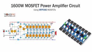
![1600W MOSFET Power Amplifier Circuit using IRFP240]()
1600W MOSFET Power Amplifier Circuit Diagram using IRFP240
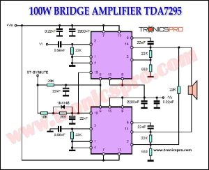
![100W Bridge Amplifier TDA7295 Circuit Diagram]()
100W Bridge Amplifier TDA7295 Circuit Diagram
![1000W Amplifier Circuit Diagram 2SC5200 2SA1943]()
1000W Audio Amplifier Circuit Diagram using 2SC5200 and 2SA1943 Transistors
![Preamplifier Circuit using TL072 IC]()
Audio Preamplifier Circuit Diagram using TL072
![300W Amplifier Circuit Diagram for Subwoofer]()
300W Amplifier Circuit for Subwoofer | DIY Homemade
![Aquarium Pump Switch Circuit Diagram]()
Aquarium pump switch Circuit Diagram
![400W Stereo Amplifier Circuit using STK4050]()
400W Stereo Amplifier Circuit using STK4050