

Introduction
Embarking on the journey of audio electronics is both thrilling and rewarding, especially for beginners. In this article, we’ll discuss the realm of simplicity with a D718 Simple Amplifier Circuit Diagram, designed for novices. Utilizing 2SD718 and D882 transistors, this circuit provides a solid foundation for those taking their first steps in the world of amplifiers.
Before we explore the specifications and assembly of this beginner-friendly amplifier, let’s understand the key components:
2SD718 Transistor:
Voltage Rating: 120V
Current Rating: 8A
Power Dissipation: 80W
Gain (hFE): 40-320
Package: TO-3P
D882 Transistor:
Voltage Rating: 40V
Current Rating: 3A
Power Dissipation: 25W
Gain (hFE): 60-320
Package: TO-126
These transistors form the heart of the amplifier, offering a balance of power and simplicity suitable for beginners.
D718 Simple Amplifier Circuit Diagram
Here’s a simplified circuit diagram of the D718 Simple Amplifier. This project can be built using a few basic components. The circuit diagram of this project is shown below.


More Circuit Layouts


Components List of D718 Simple Amplifier Circuit Diagram
Following is the list of all components used in this project:
- 2SD718 Transistor x 1
- D882 Transistor x 1
- 39k Resister x 1
- 2200uF Capacitor x 1
- 100uF Capacitor x 1
- 50k Potentiometer x 1
- 12V Single Power Supply
- 4 Ohms Speaker
Explanation of D718 Simple Amplifier Circuit Diagram
In this uncomplicated design, the input audio signal enters through 100uF capacitor, passing through the voltage divider network formed by 39k resister. The transistors 2SD718 and D882 work together to amplify the signal, creating an output that is then filtered by the output capacitor 2200uF. This straightforward configuration ensures an easy-to-understand yet effective amplifier.
Building the Amplifier:
For beginners, the assembly process is crucial. Here’s a step-by-step guide to crafting this simple amplifier:
Component Placement: Begin by placing and soldering the 2SD718 and D882 transistors, resistors (39k), and capacitors (100uF, 2200uF) onto the PCB.
Power Supply Connection: Connect a suitable power supply voltage, typically in the range of 12-18V, to the amplifier circuit.
Testing: Before connecting a speaker, conduct initial amplifier testing using a signal generator and an oscilloscope. Adjust biasing if necessary to ensure optimal performance.
Speaker Connection: Once testing is successful, connect the amplifier to a speaker with an impedance matching the circuit’s specifications.
Conclusion
In the realm of audio electronics, simplicity often leads to a deeper understanding. The D718 Simple Amplifier Circuit Diagram, featuring 2SD718 and D882 transistors, offers a gateway for beginners to explore the fundamentals of amplifier construction.
By following the straightforward circuit diagram and assembly steps, novices can gain hands-on experience in building functional audio amplifiers. The chosen transistors strike a balance between power capabilities and ease of use, making this circuit an ideal starting point for those entering the exciting world of electronics.
More projects, You may like:
- Video Transmitter DIY Homemade FM Radio Transmitter
- Adjustable Power Supply DIY Battery Charger
- 12V-220V 500 Watt inverter DIY Homemade
- MPPT Solar Charge Controller DIY Homemade
- DIY LA4440 bass amplifier homemade
For more project and circuit diagrams, you can go through the Schematics in the main menu where you can find many interesting projects and circuit diagrams like audio amplifier circuits, voltage booster circuit, and timer circuits etc. Feel free to check them out!
Thank you for visiting the article.
You may also like:
![1000W Power Amplifier Circuit using 2SC5200 & 2SA1943]()
1000W Power Amplifier Circuit Diagram using 2SC5200 & 2SA1943
![AC Power Amplifier Circuit Diagram]()
AC Power Amplifier Circuit Diagram
![150W MOSFET Audio Power Amplifier Circuit Diagram thumb]()
150W MOSFET Audio Power Amplifier Circuit Diagram
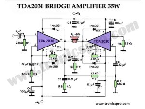
![TDA2030 Bridge Amplifier 35W Circuit Diagram]()
TDA2030 Bridge Amplifier 35W Circuit Diagram
![2N3055 MJ2955 Class-AB Amplifier Circuit Diagram]()
2N3055 & MJ2955 Class-AB Amplifier Circuit Diagram
![Unity Gain Amplifier LM1877 Circuit Diagram]()
Unity Gain Amplifier LM1877 Circuit Diagram
![Power Amplifier Circuit with Active Tone Control using 2N3055-min]()
Power Amplifier Circuit with Active Tone Control using 2N3055 Transistors
![40W Dual Bridge Amplifier TDA7374]()
40W Dual-Bridge Amplifier TDA7374 Circuit


The schematic is wrong. The 2SD718 is connected direct to power supply.
Its very simple with minimum parts. Thanks for visiting site & comments.
Check out this video : https://tronicspro.com/diy-d718-d882-amplifier-homemade/
As Danick says above – the circuit cannot work. The transistors will get warm because they are connected across the supply, but there won’t be any amplification.
You’ve copied another incorrect circuit from the ‘net and don’t understand how it’s meant to work.
Danik&Albert, Unless there is something waiting on ur Ckt the Ckt has to work as it is basically a simple straight forward Darlington Ckt shree is high gain of around a 1000 is pretty adequate to give a reasonable sound off a line in source. It may get quite warm and def not recc for batt operation.