Introduction
Having a balanced power supply circuit is essential for many electronic devices and projects. It ensures a stable and constant flow of power, which is crucial for optimal performance. In this article, we will discuss how to create a Balanced Power Supply Circuit Diagram using the 78L15 and 79L15 ICs, along with the specifications of these ICs and the 1N4002 diodes.
The following circuit diagram showcases a design that is particularly beneficial for situations where balanced power lines with a relatively small output current are required. The diagram depicts a ±15 V supply that has the capacity for a continuous output current of 25 mA or a peak of 100 mA. By incorporating different transformers and/or voltage regulators, this supply can be adjusted to accommodate output voltages of ±5V, ±9V, ± 12V, ±18 V, and ±24 V. However, it may be challenging to obtain a negative voltage regulator for the ±18V and ±24V settings. The compact size of this supply allows for easy integration into existing equipment.
One downside of utilizing small mains transformers (with low volt-ampere ratings) for this supply is that they frequently generate relatively high no-load secondary voltages. When the specified transformer is under no-load conditions, it can provide up to 32V to the regulator inputs (measured at a mains voltage of 230V).
In certain instances, the no-load secondary voltage may exceed the maximum allowable input voltage for low-power voltage regulators. Typically, this threshold is 30V for 5-V regulators, 35V for 12-V and 15-V varieties, and 40-V for 18-V and 24-V versions. In situations where the no-load voltage is expected to approach the voltage regulator’s absolute maximum level, shunt resistors (also known as bleeders) should be applied across the transformer secondaries. To minimize unnecessary dissipation, the value of these resistors should be as high as possible. In most cases, a bleeder current of a few mA proves sufficient to reduce the regulator input voltage to a safe level.
Balanced Power Supply Circuit Diagram
This project can be designed using a few basic components. The circuit diagram of this project is shown below.

More Circuit Layouts


Components List of Balanced Power Supply Circuit Diagram
Following is the list of all components used in this project:
Overview of Balanced Power Supply Circuit Diagram
A balanced power supply makes use of both positive and negative voltages to provide a symmetrical power distribution. This is particularly useful in audio applications, where a balanced signal is required for better noise rejection and improved audio quality.
The circuit diagram for the Balanced Power Supply consists of two main components: the 78L15 and 79L15 ICs. These ICs are part of the 78xx and 79xx series voltage regulators, respectively. They are widely used in various electronic circuits due to their reliability and simplicity.
Specifications of 78L15 and 79L15 ICs:
- 78L15 IC: The 78L15 IC is a positive voltage regulator that provides a fixed output voltage of +15V. Some of the key specifications of this IC are as follows:
- Input Voltage Range: The recommended input voltage range for the 78L15 IC is between +17V and +35V.
- Output Voltage: The output voltage is fixed at +15V, which is regulated to within ±4% of the nominal value.
- Current Limit: The maximum output current that the 78L15 IC can handle is 100mA.
- Thermal Shutdown: The IC includes thermal shutdown protection to prevent damage from excessive heat.
- Package Type: The 78L15 IC is available in various package types, such as TO-92, SOT-89, and SOIC-8.
- 79L15 IC: The 79L15 IC, on the other hand, is a negative voltage regulator that provides a fixed output voltage of -15V. It complements the 78L15 IC by producing a symmetrical power supply. The specifications of the 79L15 IC are similar to that of the 78L15 IC, with the exception of the output voltage being negative.
Specifications of 1N4002 Diode:
In the Balanced Power Supply Circuit, four diodes are used for rectification purposes. The 1N4002 diode is a widely used general-purpose diode. Some of its specifications are as follows:
- Peak Repetitive Reverse Voltage: The 1N4002 diode can withstand a peak repetitive reverse voltage of up to 100V.
- Average Rectified Forward Current: This diode can handle an average forward current of 1A.
- Maximum Forward Voltage Drop: The maximum forward voltage drop across the diode is approximately 1V when the forward current is 1A.
- Reverse Recovery Time: The 1N4002 diode has a reverse recovery time of 30μs, which is the time taken for the diode to recover from reverse bias to forward bias.
- Package Type: The diode is available in various packages, such as DO-41, DO-204AL, and DO-27.
Conclusion of Balanced Power Supply Circuit Diagram
A Balanced Power Supply Circuit Diagram DIY using the 78L15 and 79L15 ICs is a simple and effective way to achieve a symmetrical power distribution for better audio quality and noise rejection. The 78L15 and 79L15 ICs provide a regulated output voltage of +15V and -15V, respectively, with a current limit of 100mA. The 1N4002 diode used in the circuit ensures proper rectification of the AC input voltage. By implementing this circuit, you can ensure a stable and balanced power supply for your electronic projects.
More projects, You may like:
- Video Transmitter DIY Homemade FM Radio Transmitter
- Adjustable Power Supply DIY Battery Charger
- 12V-220V 500 Watt inverter DIY Homemade
- 12V-220V H-Bridge Inverter DIY Homemade
- MPPT Solar Charge Controller DIY Homemade
- 18650 battery bank free charge protection module
- D718 B688 Bass Amplifier Homemade DIY
- C5200 Bass Amplifier DIY Homemade with Volume
- DIY LA4440 bass amplifier homemade
- C5200 A1943 TDA2030 Amplifier DIY Homemade
For more project and circuit diagrams, you can go through the Schematics in the main menu where you can find many interesting projects and circuit diagrams like audio amplifier circuits, voltage booster circuit, battery charger circuit and timer circuits etc., which are all beginner circuit projects. Feel free to check them out!
Thank you for visiting the article.
You may also like:
![Selective Door Chime Circuit Diagram]()
Selective Door Chime Circuit Diagram
![500W MOSFET Amplifier Circuit Diagram using IRFP448]()
500W MOSFET Amplifier Circuit Diagram using IRFP448 | DIY
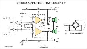
![Stereo Amplifier Single Supply Circuit Diagram]()
Stereo Amplifier Single Supply Circuit Diagram
![Low Pass Filter Circuit Subwoofer using TL072 IC]()
Subwoofer Filter Circuit using TL072 for Low Pass
![150 Watt Lamp Dimmer Circuit Diagram]()
150 Watt Lamp Dimmer Circuit Diagram
![100 Watts LM3886 Amplifier Circuit Diagram]()
100 Watts LM3886 Amplifier Circuit Diagram
![500W Amplifier Circuit using 2SC2922 & 2SA1216 SANKEN]()
500W Amplifier Circuit Diagram using 2SC2922 & 2SA1216 SANKEN
![100W Amplifier Circuit Diagram using TIP36 Transistors]()
100W Amplifier Circuit Diagram using TIP36 Transistors