

Introduction
Audio amplifiers are essential components in sound systems, delivering the power needed to drive speakers and produce high-quality sound. MOSFET-based amplifiers are popular due to their efficiency, reliability, and low distortion characteristics. In this article, we will explore the design and construction of a 100W MOSFET audio amplifier circuit using IRF530 and IRF9530 in the output stage, along with BC546 and BC556 transistors in the driver and preamplifier sections.
Specifications of Components Used:
IRF530:
Drain-Source Voltage (VDS): 100V
Continuous Drain Current (ID): 14A
On-Resistance (RDS(on)): 0.4 ohms
Power Dissipation (PD): 75W
IRF9530:
Drain-Source Voltage (VDS): -100V
Continuous Drain Current (ID): -12A
On-Resistance (RDS(on)): 1.5 ohms
Power Dissipation (PD): 88W
BC546:
Collector-Emitter Voltage (VCEO): 65V
Collector Current (IC): 100mA
Power Dissipation (PD): 500mW
BC556:
Collector-Emitter Voltage (VCEO): -65V
Collector Current (IC): -100mA
Power Dissipation (PD): 500mW
100W MOSFET Audio Amplifier Circuit Diagram using IRF530 & IRF9530
This project can be built using a few basic components. The circuit diagram of this project is shown below.


Caution: Website contains information on high voltage circuits. Proceed at your own risk, ensuring proper knowledge and precautionary measures to prevent electric shock or injury.
More Circuit Layouts


Components List of 100W MOSFET Audio Amplifier Circuit Diagram using IRF530 & IRF9530
Following is the list of all components used in this project:
Transistors:
- IRF530 MOSFET x 1
- IRF9530 MOSFET x 1
- BC546 Transistor x 2
- BC556 Transistor x 2
Resisters:
- 4.7k Resister x 2
- 47k Resister x 2
- 560Ω Resister x 1
- 15k Resister x 1
- 1.2k Resister x 1
- 2.2k Resister x 1
- 2.7k Resister x 2
- 10k Resister x 1
- 300Ω Resister x 1
- 820Ω Resister x 1
- 680Ω Resister x 1
- 10Ω/2W Resister x 1
Capacitors:
- 220pF Capacitor x 1
- 47uF Capacitor x 2
- 100uF Capacitor x 3
- 68nF Capacitor x 1
Miscellaneous:
- 1N4002 Diode x 1
- ±35V Symmetrical Power Supply
- 4Ω Speaker
Explanation of 100W MOSFET Audio Amplifier Circuit Diagram using IRF530 & IRF9530
The heart of this audio amplifier circuit lies in the output stage, where the IRF530 and IRF9530 MOSFET transistors operate in a push-pull configuration. This setup ensures efficient power delivery to the speakers while maintaining low distortion levels. The BC546 and BC556 transistors serve as drivers, controlling the flow of current through the MOSFETs.
The preamplifier section, consisting of BC546 and BC556 transistors, amplifies the input signal before it reaches the output stage. This amplification process helps boost the audio signal to a level suitable for driving the MOSFETs, ensuring optimal performance and fidelity.
Conclusion
The 100W MOSFET audio amplifier circuit employing IRF530 and IRF9530 in the output section, along with BC546 and BC556 in the driver and preamplifier sections, offers a robust solution for high-fidelity audio reproduction. With careful design and component selection, this amplifier delivers clean, powerful sound suitable for a variety of audio applications. By understanding the circuit design and component specifications, enthusiasts can build and customize audio amplifiers to suit their specific needs.
More projects, You may like:
- Video Transmitter DIY Homemade FM Radio Transmitter
- Adjustable Power Supply DIY Battery Charger
- 12V-220V 500 Watt inverter DIY Homemade
- MPPT Solar Charge Controller DIY Homemade
- DIY LA4440 bass amplifier homemade
For more project and circuit diagrams, you can go through the Schematics in the main menu where you can find many interesting projects and circuit diagrams like audio amplifier circuits, voltage booster circuit, battery charger circuit and timer circuits etc., which are all beginner circuit projects. Feel free to check them out!

Thank you for visiting the article.
You may also like:
![Power Supply Audo-On-Off Switch Circuit]()
Power Supply Auto-On-Off Switch Circuit Diagram
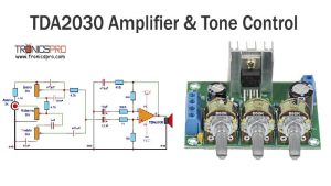
![TDA2030 Amplifier with Tone Control Circuit Diagram]()
TDA2030 Amplifier with Tone Control Circuit Diagram
![Polarity Protection Circuit Diagram]()
Polarity Protection Circuit Diagram
![200W Amplifier Circuit Diagram using NJW21193 & NJW21194 Transistors]()
200W Bass Amplifier Circuit Diagram using NJW21194 & NJW21193
![260W Amplifier Circuit Diagram using TIP140 & TIP145-min]()
260W Amplifier Circuit Diagram using TIP140 & TIP145
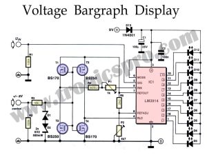
![Voltage Bargraph Display Circuit Diagram]()
Voltage Bargraph Display Circuit Diagram
![Simple Bass Amplifier Circuit using TIP3055 & TDA2030]()
Bass Amplifier Circuit Diagram using TIP3055 & TDA2030
![400W Amplifier Circuit Diagram using 2SC2922 & 2SA1216]()
400W Amplifier Circuit Diagram using 2SC2922 & 2SA1216


Hi everyone,
there’s an error in this schematic:
The base of BC546, part of the bootstrap circuit, should NOT tied to ground via the 300Ohm resistor, but floating and tied only to the 10KOhm resistor.