Introduction
The Switchable AC Power Supply circuit diagram provides a versatile solution for obtaining different AC voltages by utilizing the principle of connecting secondary windings of transformers in series. This circuit employs two transformers, X1 and X2, with multiple windings that can be selectively connected using a rotary switch. By manipulating the phase relationship between the voltages induced in the windings, a wide range of AC voltages can be obtained at the output. This project not only demonstrates the practical application of transformer theory but also highlights the importance of correctly measuring and analyzing voltages to ensure the desired output.
With reference to the following circuit diagram of Switchable AC Power Supply, we explained that the voltages induced in the secondary windings of a transformer can be connected in series to buck or boost a.c. voltage. If the two voltages are in phase, they will add up; and if they are in phase opposition, the output will be the algebraic difference of the two voltages. This principle is used in this circuit to get different a.c. voltages.
Switchable AC Power Supply Circuit Diagram
This project can be designed using a few basic components. The circuit diagram of this project is shown below.

More Circuit Layouts


Working Explanation of Switchable AC Power Supply
Two transformers, X1 with two secondary windings of 9 V and X2 with two windings of 6 V can be connected in different ways by a two-pole six-way rotary switch SW1a and SW1b. This switch skips two possible combinations, 21 V and 30 V, while all other values, 3 V, 6 V, 9 V, 12 V, 18 V and 24 V are available at the output.
In case you do not get the voltages as shown in Figure 14.2, one of the secondary winding may be in reverse phase. This situation can be easily analyzed and corrected by a.c. voltmeter measurements. Remember that the open circuit voltage of secondary windings can be a little higher than the rated voltage. Also, ensure that the switch used is a break-before-make type. Otherwise short circuits will result during switching.
For experimenters, low power transformers will do. If you want to use bigger transformers, be sure to see that the switch contacts are also rated accordingly.
Conclusion of Switchable AC Power Supply
In conclusion, the Switchable AC Power Supply circuit diagram offers a practical and flexible solution for obtaining different AC voltages. By harnessing the principles of transformer theory, this circuit allows for the series connection of secondary windings to achieve voltage bucking or boosting. With the use of a two-pole six-way rotary switch, various voltage combinations can be selected, providing output options ranging from 3 V to 24 V. It is crucial to ensure that the windings are in the correct phase and to use a break-before-make type switch to prevent short circuits. Overall, this project allows experimenters to explore the behavior of transformers and serves as a valuable learning tool for understanding the principles of AC power supply circuits.
More projects, You may like:
- Video Transmitter DIY Homemade FM Radio Transmitter
- Adjustable Power Supply DIY Battery Charger
- 12V-220V 500 Watt inverter DIY Homemade
- 12V-220V H-Bridge Inverter DIY Homemade
- MPPT Solar Charge Controller DIY Homemade
- 18650 battery bank free charge protection module
- D718 B688 Bass Amplifier Homemade DIY
- C5200 Bass Amplifier DIY Homemade with Volume
- DIY LA4440 bass amplifier homemade
- C5200 A1943 TDA2030 Amplifier DIY Homemade
For more project and circuit diagrams, you can go through the Schematics in the main menu where you can find many interesting projects and circuit diagrams like audio amplifier circuits, voltage booster circuit, battery charger circuit and timer circuits etc., which are all beginner circuit projects. Feel free to check them out!
Thank you for visiting the article.
You may also like:
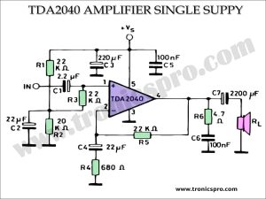
 TDA2040 Power Amplifier 25W Single Supply
- Remote Controlled Touch Dimmer Circuit Diagram
- Unity Gain Amplifier LM1877 Circuit Diagram
- Bass Tone Control Circuit Diagram using LM324 Opamp
- 1000W Amplifier Circuit Diagram using C3858 & A1494 Transistors
- 150W Audio Amplifier Circuit Diagram TIP3055
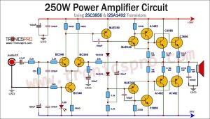
- 1000W Amplifier Circuit Diagram based 2SC5200 & 2SA1943 | Bell Power
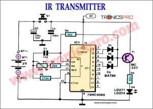
- IR Transmitter Circuit Diagram (Infrared)