

Introduction
A low pass filter circuit Bass Booster is an essential component in audio systems that enhances the bass frequencies of an audio signal. The JRC4558 IC, an integrated circuit, is widely used in low pass filter circuits due to its superior performance and versatility. This circuit is known for its ability to isolate low-frequency sounds and eliminate high-frequency noise, resulting in an improved audio experience. In this article, we will explore the functioning of the low pass filter circuit Bass Booster using the JRC4558 IC, highlighting its unique features and benefits.
When we listen to music or any sound, there are instances where we feel vibrations or shaking either within ourselves or objects in our surroundings. These vibrations are caused by low or bass sounds, which have frequencies ranging from 25Hz to 150Hz. Sounds beyond these frequencies are considered mid or high frequencies. In this article, we provide you with a low pass filter Bass-Booster circuit that covers frequencies from 20Hz to 150Hz, ideal for subwoofers.
If you’re in need of a circuit that specifically focuses on low audio frequency (bass), then this JRC4558 low pass filter bass-booster circuit is perfect for you! It effectively removes high frequencies from audio, leaving only the low frequencies between 25Hz and 150Hz.
Given that audio frequencies are categorized into different ranges such as low, mid, and high frequencies (Hz to KHz), it seems like you are interested in cutting off the high frequencies and focusing solely on the low frequencies. This Low Pass Filter Bass-Booster circuit will help you achieve that.
Circuit Diagram of Low Pass Filter Bass-Booster
This project can be designed using a few basic components. The circuit diagram of this project is shown below.

More Circuit Layouts


Components List of Low Pass Filter Bass-Booster
Following is the list of all components used in this project:
- JRC4558 IC x 1
- 1KΩ Resister x 3
- 5KΩ Resister x 1
- 10KΩ Resister x 3
- 51KΩ Resister x 1
- 22µF Capacitor x 2
- 100nF Capacitor x 1
- 0.63pF Capacitor x 1
- 150nF Capacitor x 1
Working Explanation of Low Pass Filter Bass-Booster
The output of this circuit is connected to the input of a subwoofer amplifier, which is responsible for driving the subwoofer speaker. The circuit is built around the op-amp integrated circuit JRC4558 and utilizes a dual rail power supply, consisting of positive and negative rails as well as a ground (GND) connection.
Conclusion
In conclusion, the low pass filter circuit Bass Booster utilizing the JRC4558 IC is a highly effective solution for enhancing the bass frequencies in audio systems. Its ability to eliminate high-frequency noise while isolating low-frequency sounds ensures a superior audio experience. By incorporating this circuit into audio systems, users can enjoy a more robust and immersive bass output. The JRC4558 IC’s versatility and superior performance make it a popular choice for audio signal processing, providing reliable and high-quality bass enhancement. With its unique features and benefits, the low pass filter circuit Bass Booster using the JRC4558 IC proves to be an essential component in achieving exceptional sound reproduction.
More projects, You may like:
- Video Transmitter DIY Homemade FM Radio Transmitter
- Adjustable Power Supply DIY Battery Charger
- 12V-220V 500 Watt inverter DIY Homemade
- 12V-220V H-Bridge Inverter DIY Homemade
- MPPT Solar Charge Controller DIY Homemade
- 18650 battery bank free charge protection module
- D718 B688 Bass Amplifier Homemade DIY
- C5200 Bass Amplifier DIY Homemade with Volume
- DIY LA4440 bass amplifier homemade
- C5200 A1943 TDA2030 Amplifier DIY Homemade
For more project and circuit diagrams, you can go through the Schematics in the main menu where you can find many interesting projects and circuit diagrams like audio amplifier circuits, voltage booster circuit, battery charger circuit and timer circuits etc., which are all beginner circuit projects. Feel free to check them out!
Thank you for visiting the article.
You may also like:
![Balanced Microphone Preamplifier Circuit Diagram]()
Balanced Microphone Preamplifier Circuit Diagram
![Preamplifier Circuit Diagram Low Noise DIY]()
Preamplifier Circuit Diagram Low Noise DIY
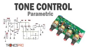
![Parametric Tone Control Circuit using LM4558 IC]()
Parametric Tone Control Circuit Diagram using LM4558 IC
![500W Power Amplifier Circuit using 2SC5200 & 2SA1943]()
500W Power Amplifier Circuit Diagram using 2SC5200 & 2SA1943
![100W C5200 Bridge Amplifier Circuit]()
100W C5200 Bridge Amplifier Circuit Diagram
![TDA2611 Audio Power Amplifier Circuit Diagram]()
TDA2611 Audio Power Amplifier Circuit Diagram
![400W Audio Amplifier Circuit Diagram pcb2]()
400W Power Amplifier Circuit Diagram | Audio Amplifier
![1400W Audio Power Amplifier Circuit using 2SC2912 & 2SA1216]()
1400W Audio Power Amplifier Circuit Diagram using 2SC2922 & 2SA1216


low pass filter
0,63pf ???
Typing mistake. It might be uf or nf but not pf. You can use 681J to 684J.