

Introduction
The 100W C5200 Bridge Amplifier is a power amplifier that is designed to provide high-quality sound amplification for both music and voice applications. This circuit is designed using the two C5200 NPN power transistors, which is known for its high gain and high power output capabilities. The C5200 transistor is a popular choice for power amplification applications, thanks to its excellent thermal stability, low distortion, and high bandwidth.
The 100W C5200 Bridge Amplifier circuit is a bridge-type amplifier, which means it uses two transistors to amplify the signals, producing a higher output power than a single-ended amplifier.
The circuit design of this amplifier is relatively simple, making it ideal for DIY enthusiasts and hobbyists who want to build their own high-quality amplifiers. It features a compact design, efficient power usage, and low distortion, making it suitable for use in small to medium-sized rooms.
In this article, we will explore the inner workings of the 100W C5200 Bridge Amplifier circuit, including its components, construction, and operation. We will also highlight its benefits and drawbacks, and offer tips for building and using this amplifier.
Circuit Diagram of 100W C5200 Bridge Amplifier

More Circuit Layouts


Working Explanation
of 100W C5200 Bridge Amplifier
The 100W C5200 Bridge Amplifier circuit is composed of several components, each with a specific function in the circuit. The main components of this circuit include:
- Power Transistors: The C5200 transistor is the main power transistor in this amplifier. It has a maximum power output of 150 watts, making it capable of driving high power speakers.
- Power Supply: The circuit requires a dual power supply of +/- 55-volts to operate. The power supply provides the necessary voltage and current to drive the transistors.
- Load Resistors: Load resistors are used to simulate the load that the amplifier will be driving. This helps to ensure that the amplifier is operating within its design specifications.
- Filter Capacitors: The filter capacitors are used to filter out any noise or disturbances in the power supply, ensuring that the output signal is clean and free from distortion.
- Input Capacitors: The input capacitors are used to block any DC voltage from the source, ensuring that the amplifier is not overloaded.
- Feedback Resistors: The feedback resistors are used to provide negative feedback to the amplifier, reducing the gain and improving the stability of the circuit.
Construction of 100W 2sc5200 Bridge Amplifier:
The construction of the 100W C5200 Bridge Amplifier circuit is relatively straightforward, making it an ideal project for beginners. The circuit requires a PCB, which can be easily designed and printed using a computer-aided design (CAD) program.
Once the PCB is ready, the components can be mounted on it using a soldering iron. The power transistors, filter capacitors, and load resistors are mounted on large heat sinks to dissipate the heat generated during operation.
The input and feedback resistors are mounted near the input and output terminals, while the power supply and filter capacitors are located at the back of the PCB.
Components List
of 100W C5200 Bridge Amplifier
- C5200 Transistor x 2
- 10uf Capacitor x 1
- 82 Ohm Resister x 1
- 47K Resister x 1
- 100k Resister x 1
- 50k Potentiometer x 1
- Mobile Jack Pin
- 4 Ohm Speaker
- 12V Power Supply
Conclusion
The 100W C5200 Bridge Amplifier is a high-quality power amplifier circuit that offers excellent performance and efficiency. It is easy to build and provides a low distortion output, making it suitable for use in various applications.
The use of the C5200 NPN power transistor and the bridge amplifier design allows it to provide high output power, making it ideal for driving high power speakers. Additional features, such as the input and feedback resistors and the filter capacitors, ensure that the amplifier provides a clean, accurate, and stable output.
Overall, the Amplifier is an excellent choice for DIY enthusiasts and hobbyists looking to build their own high-quality power amplifier. With its compact design, efficiency, and low distortion, it is perfect for use in small to medium-sized rooms.
More projects, You may like:
- Video Transmitter DIY Homemade FM Radio Transmitter
- Adjustable Power Supply DIY Battery Charger
- 12V-220V 500 Watt inverter DIY Homemade
- 12V-220V H-Bridge Inverter DIY Homemade
- MPPT Solar Charge Controller DIY Homemade
- 18650 battery bank free charge protection module
- D718 B688 Bass Amplifier Homemade DIY
- C5200 Bass Amplifier DIY Homemade with Volume
- DIY LA4440 bass amplifier homemade
- C5200 A1943 TDA2030 Amplifier DIY Homemade
You may also like:
![Non-Inverting AC Power Amplifier Circuit Diagram]()
Non-Inverting AC Power Amplifier Circuit Diagram
![100W Power Amplifier TDA7293 Circuit Diagram]()
100W Power Amplifier TDA7293 Class AB Circuit
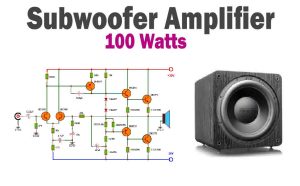
![100W Subwoofer Amplifier Circuit]()
100W Subwoofer Amplifier Circuit Diagram
![32W Amplifier TDA2050 Split-Supply Circuit Diagrm]()
32W Amplifier TDA2050 Split-Supply Circuit
![TDA2050 Subwoofer Amplifier Circuit Diagram using JRC4558]()
TDA2050 Subwoofer Amplifier Circuit Diagram using JRC4558 IC
![200W Power Amplifier Circuit using STK4050]()
200W Power Amplifier Circuit Diagram using STK4050
![Subwoofer Amplifier Circuit TDA2030]()
Subwoofer Amplifier Circuit Diagram using TDA2030
![100W MOSFET Audio Amplifier Circuit Diagram using IRF530 & IRF9530]()
100W MOSFET Audio Amplifier Circuit Diagram using IRF530 & IRF9530


I made this amplifier, quick and easy, perfect for beginners. The sound is real good for such few components, but what bothers me is the 5V going out to the speaker? Isn’t that very harmful for the speaker?