Introduction
Stepper motor control circuits can be used to regulate and control the speed, torque, accuracy, and position of a rotary or linear system – enabling precise movement of a given part or machine. Generally speaking, stepper motors are driven by DC current and have multiple-phase windings that create magnetic fields – which in turn cause the shaft to rotate in discrete steps when the stepper driver sends out pulses of electric current. By changing the velocity of these input signals, you can adjust the power output at any given time – ultimately allowing for highly precise and controlled movements.
Circuit Diagram
of Stepper Motor Control Circuit

More Circuit Layouts


Working Explanation
of Stepper Motor Control Circuit
The manipulation is a compact layout for using bipolar stepper motors. Driver stages IC1 (L297)‚ and IC3 (L6203) are modern types from ST Microelectronics. Due to the combination of cmos good judgment with d-mos electricity transistors, those devices need few external components. Additionally, in comparison with the previous technology of bipolar devices inclusive of the l298, the d-mos transistors drop decrease voltages so that the inner dissipation is smaller.

The input stage, IC1‚, enables the motor to proceed one step for each pulse at its input pin 18. The level at pin 17 (CW/CCW) determines whether the motor rotates clockwise or anticlockwise. The level at pin 19 comes to a decision on whether the motor movements are complete or half steps for every pulse at pin 18. In normal operation, pin 20(reset), pin 11 (control), and pin 10 (enable) should be linked to the +5 V supply. Pin 1 (sync) is an output used when several L297s are driven in tandem and should be left open in the present design. Pin 3 (home) is an output that indicates when outputs A, B, C, and D, assume the binary code 0101 and is not used in the present design. The other pins are of less importance and will in most cases not be used at all - further information may be obtained from the Internet address http://www.us.st.com

For the reason that modern-day via motor coils have to not simplest be switched on and rancid, but also be reversed, the motive force ics comprise a whole bridge shaped by way of four d-mosfets. The upper two need to be driven by a potential that is higher than the supply voltage, and this is obtained with the aid of a bootstrap circuit (C5, C6). Network R4-C11 suppresses voltage peaks across
the motor terminals. Most of the other capacitors in the diagram are decoupling (bypass) elements.
The driving force ics can cope with currents of as much as 4 A at voltages as much as 42V. For protection's sake, it's miles higher for the voltage to Continue to be nicely underneath 42 v; the current is internally limited to 4 A. Any tendency of the current to rise above this level is sensed by resistors R6 and R7, whereupon the IC is disabled. The value, R, of these resistors, must, therefore, be in line with Im, the motor current: R=1/1m: The driver ICs are provided with internal thermal protection, but when the dissipation is large, it is advisable to mount them on a suitable heat sink. They do not get damaged by heat, but they do switch off the motor when the temperature rises above the maximum specified temperature.
Finally, it should be noted that IC1‚ operates from a +5 V supply (via K1) from which it draws a current of about 50 mA. The voltage at pins 0 and + is intended for the stepper motor and should be equal to, or a little higher than, the rated motor voltage.
Components List
of Stepper Motor Control Circuit
Resistors:- R] = 22 k
- R2 = 3.9 k
- R3 = 1 k
- R4, R5 = 10 k
- R6, R7 = 0.5 ohm, 3 W (see text)
Capacitors: - Câ‚ = 3.3 nF
- C2, C9, C10 = 100 nF
- C3, C4 = 220 nF
- C5-Cg = 15 nF
- C11, C12 = 22 nF
- C13 = 10 uF, 63 V, rad.
Semiconductors: - IC1 = L297 (ST Microelectronics)
- IC2, IC3 = L6203 (ST Microelectronics)
Miscellaneous: - K1 = 10-way header
- PC1-PC6 = PCB pins
- L1, L2 = bipolar stepper motor
More Circuits, You May Like:
- 100 Watts LM3886 Amplifier Circuit Diagram
- Auto Volume Tone Control Circuit Diagram
- Build Your Own Stereo Amplifier with TDA1552 DIY
- Stereo Amplifier NE5532 Circuit Diagram
- Fifth-Order Low-Pass Filter Circuit Diagram
- Ultra-Low-Noise Preamplifier Circuit Diagram
- Amplifier Drive Indicator Circuit Diagram
- Car Booster Amplifier Adaptor Circuit Diagram
- Digital Audio Input Selector DIY Circuit
- Bass amplifier for surround sound
Conclusion
The use of stepper motor controls is a great way to ensure precise positioning and orientation of workpieces and other objects in any manufacturing process. With the right hardware and software, it can be easy to configure and control stepper motors for various applications in both commercial and industrial settings. The main benefit of using stepper motors is their ability to accurately position objects with minimal power consumption. It also features an interactive feedback system, making it easier for users to monitor the progress of their projects or devices. Moreover, stepper motors have the potential to reduce costs associated with maintenance due to its reliable performance over time even at extreme temperatures and conditions. All in all, when used properly, stepper motor control can be an effective tool in enhancing speed and accuracy on many different tasks.
You may also like:
![Power Amplifier Circuit using D1047 & B817 - ROTEL RA840B]()
Power Amplifier Circuit Diagram using D1047 & B817 - ROTEL RA840B
![TDA2030 Amplifier Single Supply Circuit Diagram]()
TDA2030 Amplifier Single Supply Circuit Diagram
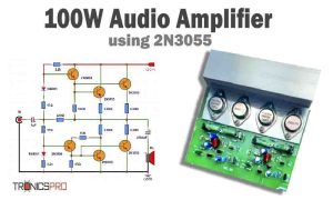
![100W Audio Amplifier Circuit Diagram using 2N3055 IC 2]()
100W Audio Amplifier Circuit Diagram using 2N3055
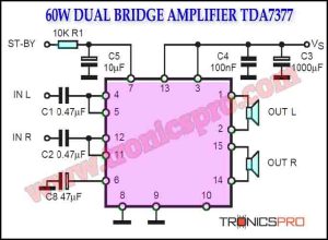
![60W Double-Bridge Stereo Amplifier using TDA7377]()
60W Double-Bridge Stereo Amplifier using TDA7377
![600W Audio Power Amplifier Circuit using 2SC5200 & 2SA1943]()
600W Audio Power Amplifier Circuit Diagram using 2SC5200 & 2SA1943 - APEX BX22
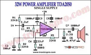
![32W Power Amplifier TDA2050 Single Supply Circuit Diagrm]()
32W Power Amplifier TDA2050 Single Supply
![Bass Booster Circuit Diagram using Single Transistor]()
Bass Booster Circuit Diagram using Single Transistor 2N2222
![20A Current Monitor Circuit Diagram]()
20A Current Monitor Circuit Diagram