Introduction
A battery discharger is a very useful tool for those who need to discharge batteries quickly and efficiently. A circuit can be used to test the capacity of a battery or to prepare it for storage. In this article, we will be focusing on a battery discharger circuit diagram that uses two BC639 transistors.
Before we dive into the circuit diagram, it is important to understand the basic functioning of a transistor. A transistor is a three-terminal device that can amplify or switch electronic signals. In our circuit diagram, we will be using two BC639 transistors connected in a Darlington configuration. A Darlington configuration is simply two transistors connected in a way that amplifies the current flowing through them.
Circuit Diagram of Battery Discharger

More Circuit Layouts


Advantages of Battery Discharger Circuit Diagram
- The circuit is simple and easy to build.
- It can discharge batteries quickly and efficiently, making it a useful tool for testing the capacity of a battery or preparing it for storage.
- The circuit is inexpensive as it uses commonly available components.
- The circuit can be easily modified to suit different battery voltages.
Conclusion:
In conclusion, a Battery Discharger using two BC639 transistors can be a useful tool for those who need to discharge batteries quickly and efficiently. The circuit is simple, easy to build, and can be modified to suit different battery voltages. The circuit can be used to test the capacity of a battery or to prepare it for storage. Overall, this circuit is an excellent example of how simple electronic circuits can be used to solve real-world problems.
More projects, You may like:
- Video Transmitter DIY Homemade FM Radio Transmitter
- Adjustable Power Supply DIY Battery Charger
- 12V-220V 500 Watt inverter DIY Homemade
- 12V-220V H-Bridge Inverter DIY Homemade
- MPPT Solar Charge Controller DIY Homemade
- 18650 battery bank free charge protection module
- D718 B688 Bass Amplifier Homemade DIY
- C5200 Bass Amplifier DIY Homemade with Volume
- DIY LA4440 bass amplifier homemade
- C5200 A1943 TDA2030 Amplifier DIY Homemade

You may also like:
![Power Amplifier MC1538R Circuit Diagram]()
Power Amplifier MC1538R Circuit Diagram
![LM2574 Switch-Mode Power Supply Circuit Diagram]()
LM2574 Switch-Mode Power Supply Circuit
![400W Stereo Amplifier Circuit using STK4050]()
400W Stereo Amplifier Circuit using STK4050
![Overload Protection Circuit Diagram]()
Overload Protection Circuit Diagram
![Balanced Power Supply Circuit Diagram]()
Balanced Power Supply Circuit Diagram
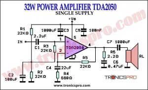
![32W Power Amplifier TDA2050 Single Supply Circuit Diagrm]()
32W Power Amplifier TDA2050 Single Supply
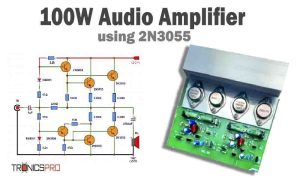
![100W Audio Amplifier Circuit Diagram using 2N3055 IC 2]()
100W Audio Amplifier Circuit Diagram using 2N3055
![500W Power Amplifier Circuit Diagram using IRFP240 & IRFP9240 MOSFET]()
500W Power Amplifier Circuit Diagram using IRFP240 & IRFP9240 MOSFETs