Introduction
A bass preamplifier circuit diagram for a subwoofer is a crucial component in any audio setup. It helps to enhance the bass frequencies, allowing for a richer and more immersive audio experience. In this article, we will discuss a bass preamplifier circuit diagram for subwoofer that utilizes BC546 and BC556 transistors. These transistors are widely used and provide excellent performance in audio amplification applications.
BC546 Transistor Specification:
- NPN (Negative-Positive-Negative) bipolar junction transistor
- Low noise and high gain characteristics make it suitable for use in audio amplifiers
- Maximum collector current (IC) rating of 100mA
- Maximum collector-base voltage (VCBO) rating of 80V
- Maximum emitter-base voltage (VEBO) rating of 6V
- DC current gain (hFE) ranging from 110 to 800
BC556 Transistor Specification:
- PNP (Positive-Negative-Positive) bipolar junction transistor
- High voltage and high current gain characteristics make it suitable for audio amplification
- Maximum collector current (IC) rating of 100mA
- Maximum collector-base voltage (VCBO) rating of 80V
- Maximum emitter-base voltage (VEBO) rating of 5V
- DC current gain (hFE) ranging from 110 to 800
Bass Preamplifier Circuit Diagram for Subwoofer
The bass preamplifier circuit makes use of BC546 and BC556 transistors to optimize the bass frequencies. The schematic diagram is as follows:


Caution: Website contains information on high voltage circuits. Proceed at your own risk, ensuring proper knowledge and precautionary measures to prevent electric shock or injury.
More Circuit Layouts


Components List of Bass Preamplifier Circuit Diagram for Subwoofer
Following is the list of all components used in this project:
Transistors:
Resisters:
- 68K Resistors x 2
- 680K Resistor x 1
- 220K Resistor x 1
- 33K Resistor x 1
- 2K2 Resistor x 1
- 5K6 Resistor x 1
- 330R Resistors x 2
- 47K Resistor x 1
- 18K Resistor x 1
- 4K7 Resistor x 1
- 1K Resistor x 1
- 1K5 Resistor x 1
- 100K Resistors x 3
- 10K Resistor x 1
- 10K Linear Potentiometer x 1
- 10K Log. Potentiometer x 1
Capacitors:
- 10µF 63V Electrolytic Capacitors x 5
- 47µF 63V Electrolytic Capacitor x 1
- 47pF 63V Ceramic Capacitor x 1
- 220nF 63V Polyester Capacitor x 1
- 470nF 63V Polyester Capacitor x 1
- 100nF 63V Polyester Capacitor x 1
- 220µF 63V Electrolytic Capacitor x 1
Explanation of Bass Preamplifier Circuit Diagram for Subwoofer
This circuit consists of two stages – the input stage and the output stage. The input stage is based on the BC546 and BC556 transistors, while the output stage utilizes the BC546 transistor.
The BC546 and BC556 transistors amplify the input signal and create a high impedance output. It is connected in a common emitter configuration, and the input audio signal is coupled via a coupling capacitor, 10µF. The 220k resistor provides the necessary biasing for the transistors. The amplified output signal is then passed through several components to the BC546 transistor for the output.
The BC546 transistor works as a buffer and drives the subwoofer speaker. The output signal is filtered using a low pass filter circuit in between. This helps to remove any high-frequency noise, focusing solely on the bass frequencies.
Conclusion
Utilizing the BC546 and BC556 transistors in a bass preamplifier circuit diagram for a subwoofer provides an effective way to enhance the audio experience. These transistors offer excellent performance and are well-suited for audio amplification applications. By incorporating this circuit, the bass frequencies can be optimized, resulting in a more immersive and enjoyable listening experience.
More projects, You may like:
- Video Transmitter DIY Homemade FM Radio Transmitter
- Adjustable Power Supply DIY Battery Charger
- 12V-220V 500 Watt inverter DIY Homemade
- MPPT Solar Charge Controller DIY Homemade
- DIY LA4440 bass amplifier homemade
For more project and circuit diagrams, you can go through the Schematics in the main menu where you can find many interesting projects and circuit diagrams like audio amplifier circuits, voltage booster circuit, battery charger circuit and timer circuits etc., which are all beginner circuit projects. Feel free to check them out!

Thank you for visiting the article.
You may also like:
![100W Power Amplifier Circuit using TIP142 TIP147]()
100W Power Amplifier Circuit Diagram
![2N3055 Stereo Amplifier with Bluetooth Circuit Diagram]()
2N3055 Stereo Amplifier with Bluetooth Circuit
![200W Power Amplifier Circuit using 2SC5200 & 2SA1943]()
200W Amplifier Circuit using 2SC5200 and 2SA1943 Transistors
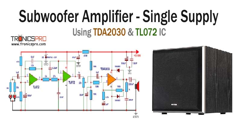
![TDA2030 Amplifier Single Supply Circuit Diagram]()
TDA2030 Amplifier Single Supply Circuit Diagram
![Car Alarm Circuit Diagram]()
Car Alarm Circuit Diagram
![400W MOSFET Power Amplifier Circuit Diagram using IRFP9240 & IRFP240]()
400W MOSFET Power Amplifier Circuit Diagram using IRFP9240 & IRFP240
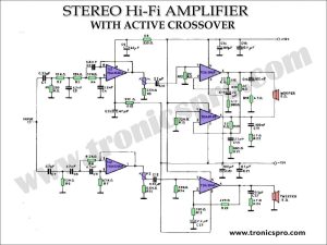
![TDA2040 Stereo Amplifier with Active Crossover]()
TDA2040 Stereo Amplifier with Active Crossover
![500W MOSFET Amplifier Cercuit using 2SK1530 & 2SJ201]()
500W MOSFET Amplifier Cercuit Diagram using 2SK1530 & 2SJ201