Introduction
The demand for powerful audio amplifiers continues to rise as audiophiles and music enthusiasts seek to enhance their listening experiences. In response to this, engineers have developed the 400W Audio Amplifier Circuit Diagram, utilizing high-quality components such as the 2SC5200 in the output section, 2SD718, 2SB688, TIP42, 2SC2229, and A1015 in the driver and preamplifier sections. In this article, we will explore the circuit diagram and specifications of these key components, highlighting their significance in delivering exceptional audio performance.
Specifications of Key Components:
Below is a vertical order list of the specifications of the key components used in the 400W Audio Amplifier Circuit Diagram:
- 2SC5200:
- Maximum Collector-Base Voltage: 230V
- Maximum Collector-Emitter Voltage: 230V
- Maximum Collector Current: 30A
- Maximum Power Dissipation: 150W
- DC Current Gain (hFE): 55-160
- Transition Frequency (fT): 30MHz
- 2SD718:
- Maximum Collector-Base Voltage: 180V
- Maximum Collector-Emitter Voltage: 150V
- Maximum Collector Current: 8A
- Maximum Power Dissipation: 70W
- DC Current Gain (hFE): 20-60
- Transition Frequency (fT): 50MHz
- TIP42:
- Maximum Collector-Base Voltage: 100V
- Maximum Collector-Emitter Voltage: 100V
- Maximum Collector Current: 6A
- Maximum Power Dissipation: 65W
- DC Current Gain (hFE): 15-75
- Transition Frequency (fT): 3MHz
- 2SC2229:
- Maximum Collector-Base Voltage: 40V
- Maximum Collector-Emitter Voltage: 40V
- Maximum Collector Current: 1.5A
- Maximum Power Dissipation: 800mW
- DC Current Gain (hFE): 60-320
- Transition Frequency (fT): 65MHz
- A1015:
- Maximum Collector-Base Voltage: 50V
- Maximum Collector-Emitter Voltage: 50V
- Maximum Collector Current: 150mA
- Maximum Power Dissipation: 400mW
- DC Current Gain (hFE): 60-380
- Transition Frequency (fT): 150MHz
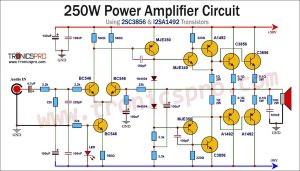
400W Amplifier Circuit Diagram using 2SC5200
This project can be built using a few basic components. The circuit diagram of this project is shown below.


Caution: Website contains information on high voltage circuits. Proceed at your own risk, ensuring proper knowledge and precautionary measures to prevent electric shock or injury.
More Circuit Layouts


Components List of 400W Amplifier Circuit Diagram using 2SC5200
Following is the list of all components used in this project:
Transistors:
- 2SC5200 Transistor x 8
- 2SD718 Transistor x 1
- 2SB688 Transistor x 1
- TIP42 Transistor x 1
- 2SC2229 Transistor x 2
- A1015 Transistor x 2
Resistors:
- 0.33Ω/5W Resister x 8
- 4.7Ω/1W Resister x 8
- 100Ω/1W Resistor x 2
- 33Ω Resister x 1
- 150Ω Resistor x 3
- 10K Resistor x 1
- 1K Resistor x 1
- 4.7K Resister x 1
- 68KΩ Resister x 2
- 33K Resister x 1
- 3.3K Resister x 2
Capacitors:
- 100uF/80V Electrolytic Capacitor x 2
- 2.2uF/50V Electrolytic Capacitor x 1
- 10pF ceramic capacitor x 2
- 470pF (471) ceramic capacitor x 2
Miscellaneous:
- 1N4007 Diode x 3
- 18V or 24V Zener Diode x 1
- ±70V Symmetrical Power Supply
- 4Ω Speaker
Explanation of 400W Amplifier Circuit Diagram using 2SC5200
The 400W Audio Amplifier Circuit Diagram is a meticulously designed system, built to provide high power and clear audio reproduction. At its core, this circuit features the 2SC5200 transistor in the output section, responsible for delivering the amplified signal to the speakers. The 2SC5200 is a powerful transistor known for its high amplification capability and low distortion, making it an ideal choice for audio amplifiers.
To drive the 2SC5200 transistor, the circuit employs the 2SD718 and 2SB688 transistors in the driver section. These transistors ensure the proper and controlled flow of current to the output transistor, enabling it to operate efficiently and accurately reproduce the audio signal. Furthermore, the TIP42 transistor, 2SC2229, and A1015 are implemented in the preamplifier section to amplify the weak input signal, providing greater signal integrity and clarity.
Conclusion
The 400W Audio Amplifier Circuit Diagram utilizing the 2SC5200 in the output section, 2SD718, 2SB688, TIP42, 2SC2229, and A1015 in the driver and preamplifier sections, offers superb audio performance with high power capability. Each component plays a crucial role in amplifying and delivering the audio signal accurately, ensuring an enhanced listening experience for users. By understanding the specifications and capabilities of these components, audio enthusiasts and engineers can build high-quality audio amplifiers that meet their specific requirements.
More projects, You may like:
- Video Transmitter DIY Homemade FM Radio Transmitter
- Adjustable Power Supply DIY Battery Charger
- 12V-220V 500 Watt inverter DIY Homemade
- MPPT Solar Charge Controller DIY Homemade
- DIY LA4440 bass amplifier homemade
For more project and circuit diagrams, you can go through the Schematics in the main menu where you can find many interesting projects and circuit diagrams like audio amplifier circuits, voltage booster circuit, battery charger circuit and timer circuits etc., which are all beginner circuit projects. Feel free to check them out!

Thank you for visiting the article.
You may also like:
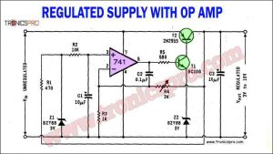
 Regulated Power Supply Circuit using Op-Amp 741
- 50W Stereo Power Amplifier Circuit Diagram STK4141
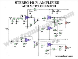
- TDA2040 Stereo Amplifier with Active Crossover
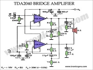
- 30W Bridge Amplifier TDA2040 Circuit Diagram
- 16 Hours Adjustable Timer Circuit Diagram
- Bridge Audio Power Amplifier Circuit Diagram
- Light to Frequency Converter Circuit
- Stereo Headphone Amplifier Circuit Diagram using NE5532