


Introduction
In today’s modern world, music has become an integral part of our lives. Whether you are a music enthusiast or an audiophile, having a good headphone amplifier is essential for experiencing high-quality sound. In this article, we will discuss a circuit diagram for a stereo headphone amplifier using a single NE5532 IC, which ensures excellent audio performance. Before delving into the circuit, let’s understand the specifications of the NE5532 IC and explore the keywords used in this article.
NE5532 IC Specification:
The NE5532 is a dual high-performance operational amplifier that offers excellent signal-to-noise ratio, low noise, and distortion, making it an ideal choice for audio applications. Its key specifications include:
- Input Offset Voltage: Typically 0.5mV
- Input Bias Current: Typically 50nA
- Supply Voltage Range: ±3V to ±20V
- Slew Rate: Typically 9V/µs
- Gain Bandwidth Product: 10MHz
- Total Harmonic Distortion: Typically 0.003%
- Output Drive Capability: ±8V (minimum)
Stereo Headphone Amplifier Circuit Diagram using NE5532 IC:
The stereo headphone amplifier circuit diagram using NE5532 IC is relatively simple and requires only a few external components. The NE5532 IC acts as the core of the amplifier and provides superb audio quality. Below is the circuit diagram:

More Circuit Layouts


Components List of Stereo Headphone Amplifier Circuit NE5532
Following is the list of all components used in this project:
- NE5532 IC x 1
- 50k Potentiometer Dual Pole x 1
- 50k Resister x 2
- 20k Resister x 4
- 15k Resister x 2
- 1uF Capacitor x 3
- 470uF Capacitor x 2
- Stereo Headphone Jack x 1
Explanation of Stereo Headphone Amplifier Circuit NE5532
The circuit operates in a standard gain configuration, utilizing both the operational amplifier‘s channels. The input signal is fed to the non-inverting terminal of the IC, and the gain is determined by the resistor values of 20k. Resistors are also used to set the feedback network, ensuring stable operation.
The NE5532 IC provides low noise and low distortion, allowing you to enjoy clear and crisp sound reproduction. It also offers a high slew rate, enabling quick response to dynamic audio signals, making it perfect for audio amplification applications.
Conclusion
The stereo headphone amplifier circuit using a single NE5532 IC is an excellent choice for those seeking high-quality audio reproduction. With its low noise, low distortion, and high slew rate characteristics, the NE5532 IC enhances the listening experience by delivering clear and accurate sound. Building this circuit can be a rewarding and enjoyable project for audio enthusiasts, providing them with a means to boost the audio quality of their headphones. Choose the NE5532 IC and enjoy immersive audio like never before.
More projects, You may like:
- Video Transmitter DIY Homemade FM Radio Transmitter
- Adjustable Power Supply DIY Battery Charger
- 12V-220V 500 Watt inverter DIY Homemade
- MPPT Solar Charge Controller DIY Homemade
- DIY LA4440 bass amplifier homemade
For more project and circuit diagrams, you can go through the Schematics in the main menu where you can find many interesting projects and circuit diagrams like audio amplifier circuits, voltage booster circuit, and timer circuits etc. Feel free to check them out!

Thank you for visiting the article.
You may also like:
![Instrumentation amplifier single supply circuit diagram]()
Instrumentation Amplifier Single-Supply Circuit
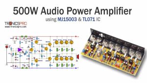
![500W Amplifier Circuit using MJ15003 & TL071]()
500W Amplifier Circuit Diagram using MJ15003 & TL071
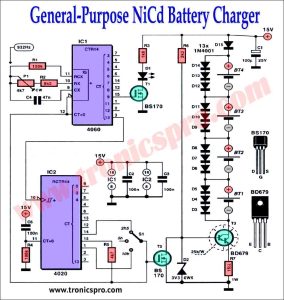
![General-Purpose NiCd Battery Charger Circuit Diagram]()
General-Purpose NiCd Battery Charger Circuit
![TDA2030 Subwoofer Amplificer Circuit with 4558 IC]()
TDA2030 Subwoofer Amplificer Circuit Diagram with 4558 IC
![Bass Amplifier Circuit Diagram using TIP42 & TIP41]()
Bass Amplifier Circuit Diagram using NE5532 OP-Amp
![2N3055 MJ2955 Class-AB Amplifier Circuit Diagram]()
2N3055 & MJ2955 Class-AB Amplifier Circuit Diagram
![13003 DIY Bass Amplifier Circuit Diagram]()
13003 DIY Bass Amplifier Circuit Diagram
![300W Amplifier Circuit Diagram for Subwoofer]()
300W Amplifier Circuit for Subwoofer | DIY Homemade


I’ve just built this amp and I got to say, it sounds great. To make it much louder, you need to replace feedback resistors from 20k to let say 100k.
Thank for sharing your hard work here.