Introduction
A subwoofer filter circuit low pass is a crucial component in any sound system that aims to reproduce low frequency audio signals with clarity and accuracy. It is responsible for isolating and amplifying the low frequency range of audio signals, allowing the subwoofer to produce deep and powerful bass tones. In this article, we will discuss the design and implementation of a subwoofer filter circuit low pass using the TL072 operational amplifier, which is known for its excellent audio performance.
The following is a simple subwoofer filter circuit for low pass that utilizes the TL072 dual op amp IC BIFET. This circuit is designed to be used with a 12V DC power source and is particularly advantageous for automotive subwoofer applications. By making slight modifications, the pass frequency of this low pass filter can be adjusted within the range of 60 to 160 Hz. The circuit primarily consists of two operational amplifiers within the TL072 chip, with U1-A functioning as a buffer and U1-B serving as the low pass filter.
Subwoofer Filter Circuit of Low Pass
This project can be designed using a few basic components. The circuit diagram of this project is shown below.

More Circuit Layouts


Components List of Subwoofer Filter Circuit Low Pass
Following is the list of all components used in this project:
- TL072 Op Amp IC x 1
- 47uF Capacitor x 1
- 100uF Capacitor x 1
- 1uF Capacitor x 2
- 0.02uF Capacitor x 1
- 10nF Capacitor x 1
- 47nF Capacitor x 1
- 33k Resister x 4
- 47k Resister x 2
- 27k Resister x 1
- 470 ohms Resister x 1
Specifications of TL072 Operational Amplifier
- Supply Voltage: The TL072 operates from a dual supply voltage range of ±6V to ±18V.
- Input Offset Voltage: The maximum input offset voltage between the two input terminals is 3 mV for TL072.
- Input Bias Current: The maximum input bias current for TL072 is 30 nA.
- Input Voltage Range: The common-mode input voltage range extends from the negative supply voltage (V-) to the positive supply voltage (V+), allowing it to accept input signals beyond the supply rails.
- Input Impedance: The input impedance for TL072 is typically 10^12 Ω.
- Output Current: The output short-circuit current of the TL072 is ±20 mA.
- Output Voltage Swing: The output voltage swing of TL072 is typically -14V to +14V, with a 2kΩ load resistance.
- Gain Bandwidth Product: The unity-gain bandwidth of the TL072 is 3 MHz.
- Slew Rate: The slew rate of the TL072 is typically 13 V/µs, indicating the maximum rate of change of the output voltage.
- Common-Mode Rejection Ratio (CMRR): The CMRR of the TL072 is typically 80 dB, indicating its ability to reject common-mode noise in the input signal.
- Operating Temperature Range: The recommended operating temperature range for the TL072 is -40°C to +125°C.
- Package Type: The TL072 is available in various package types, including DIP-8, SOIC-8, and TSSOP-8, providing flexibility for different application requirements.
It is important to note that these specifications are typical values and may vary among different manufacturers. Additionally, refer to the datasheet provided by the manufacturer for detailed specifications and further information.
Conclusion of Subwoofer Filter Circuit Low Pass
In conclusion, the subwoofer filter circuit low pass using the TL072 operational amplifier provides an effective solution for achieving high-quality low-frequency audio reproduction in sound systems. By utilizing the TL072’s exceptional audio performance, the circuit is capable of accurately isolating and amplifying bass frequencies, allowing the subwoofer to produce deep, powerful, and distortion-free bass tones. The implementation of this circuit can greatly enhance the overall audio experience, enriching the listening pleasure for sound system enthusiasts and professional audio engineers alike.
More projects, You may like:
- Video Transmitter DIY Homemade FM Radio Transmitter
- Adjustable Power Supply DIY Battery Charger
- 12V-220V 500 Watt inverter DIY Homemade
- 12V-220V H-Bridge Inverter DIY Homemade
- MPPT Solar Charge Controller DIY Homemade
- 18650 battery bank free charge protection module
- D718 B688 Bass Amplifier Homemade DIY
- C5200 Bass Amplifier DIY Homemade with Volume
- DIY LA4440 bass amplifier homemade
- C5200 A1943 TDA2030 Amplifier DIY Homemade
For more project and circuit diagrams, you can go through the Schematics in the main menu where you can find many interesting projects and circuit diagrams like audio amplifier circuits, voltage booster circuit, battery charger circuit and timer circuits etc., which are all beginner circuit projects. Feel free to check them out!

Thank you for visiting the article.
You may also like:
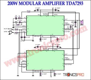
![200W Modular Amplifier TDA7293 Circuit Diagram]()
200W Modular Amplifier TDA7293 Circuit Diagram
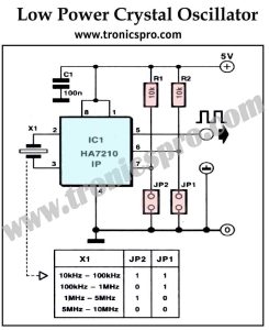
![Crystal Oscillator Low-power Circuit]()
Crystal Oscillator Low-power Circuit
![Stereo Amplifier NE5532 Circuit Diagram]()
Stereo Amplifier NE5532 Circuit Diagram
![150W Amplifier Circuit using Sanken 2SC2922]()
150W HiFi Amplifier Circuit using Sanken 2SC2922 & 2SA1216
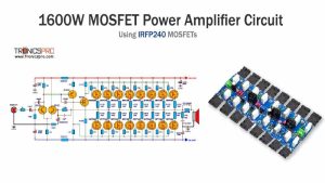
![1600W MOSFET Power Amplifier Circuit using IRFP240]()
1600W MOSFET Power Amplifier Circuit Diagram using IRFP240
![120W 4-Channel Quad Amplifier TDA7388 Circuit]()
120W 4-Channel Quad Amplifier TDA7388 Circuit
![PIR Controlled Shop Bell Circuit Diagram]()
PIR Controlled Shop Bell Circuit Diagram
![400W Stereo Amplifier Circuit using STK4050]()
400W Stereo Amplifier Circuit using STK4050