Introduction
A subwoofer amplifier circuit diagram using the TDA2030 and JRC4558 IC is an excellent solution for enhancing the bass output of your audio system. Subwoofers are specifically designed to reproduce low-frequency sounds, delivering deep and powerful bass to enrich your audio experience. In this article, we will explore the circuit diagram, specifications of the TDA2030 and JRC4558 IC, and the advantages of using this amplifier in your audio setup.
Subwoofer Amplifier Circuit Diagram TDA2030 JRC4558 IC
The subwoofer amplifier circuit utilizes the TDA2030 and JRC4558 ICs, which are renowned for their audio amplification capabilities. This circuit diagram features a straightforward design that can be easily implemented, even by electronics enthusiasts with limited experience.
This project can be built using a few basic components. The circuit diagram of this project is shown below.


More Circuit Layouts


Components List of Subwoofer Amplifier Circuit TDA2030 JRC4558
Following is the list of all components used in this project:
- TDA2030 IC x 1
- JRC4558 IC x 1
- 22k Resister x 1
- 5k Resister x 1
- 33k Resister x 1
- 10k Resister x 3
- 20k Resister x 1
- 510 Ohms Resister x 1
- 10uF/50V Capacitor x 2
- 104J Capacitor x 3
- 0.22uF Capacitor x 1
- +/-12V Power Supply
Explanation of Subwoofer Amplifier Circuit TDA2030 JRC4558
The TDA2030 is a monolithic integrated circuit in a Pentawatt package that offers high-quality audio reproduction with low distortion and noise. It operates on a wide range of power supplies and delivers a maximum output power of 14W. The TDA2030 has excellent thermal and short-circuit protection, ensuring the safety of the circuit under adverse conditions.
The JRC4558, on the other hand, is a dual operational amplifier widely used in audio applications. It has low noise performance and a high output current, making it an ideal choice for amplifying and enhancing audio signals. The JRC4558 offers excellent audio fidelity and superior output driving capabilities, ensuring your subwoofer produces clean and uninterrupted bass.
By combining the TDA2030 and JRC4558 in a single circuit, you can take advantage of their individual strengths and create a robust subwoofer amplifier. The TDA2030 operates as the power amplifier, providing ample power to drive the subwoofer, while the JRC4558 handles the audio pre-amplification to improve the overall audio performance.
Conclusion
The subwoofer amplifier circuit diagram using the TDA2030 and JRC4558 IC presents an affordable and efficient solution for boosting bass output of your audio system. With the TDA2030’s excellent power handling capabilities and the JRC4558’s superior preamplification performance, this circuit provides enhanced audio fidelity, deep bass, and low distortion.
Implementing this circuit is relatively simple, even for those with limited electronics experience, thanks to the straightforward design. By following the circuit diagram and utilizing the recommended components, you can create a subwoofer amplifier that will elevate your audio experience to new heights.
In conclusion, the TDA2030 and 4558 ICs provide an outstanding combination for constructing a subwoofer amplifier circuit. Their inherent features, such as high power handling, low distortion, and low noise performance, ensure exceptional audio quality. So, why settle for average bass performance when you can unleash the true potential of your subwoofer with this subwoofer amplifier circuit?
More projects, You may like:
- Video Transmitter DIY Homemade FM Radio Transmitter
- Adjustable Power Supply DIY Battery Charger
- 12V-220V 500 Watt inverter DIY Homemade
- 12V-220V H-Bridge Inverter DIY Homemade
- MPPT Solar Charge Controller DIY Homemade
- 18650 battery bank free charge protection module
- D718 B688 Bass Amplifier Homemade DIY
- C5200 Bass Amplifier DIY Homemade with Volume
- DIY LA4440 bass amplifier homemade
- C5200 A1943 TDA2030 Amplifier DIY Homemade
For more project and circuit diagrams, you can go through the Schematics in the main menu where you can find many interesting projects and circuit diagrams like audio amplifier circuits, voltage booster circuit, battery charger circuit and timer circuits etc., which are all beginner circuit projects. Feel free to check them out!
Thank you for visiting the article.
You may also like:
![Mains Frequency Converter Circuit Diagram]()
Mains Frequency Converter Circuit Diagram
![TDA2030 Stereo Amplifier Circuit Diagram]()
TDA2030 Stereo Amplifier Circuit Diagram
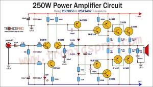
![250W Power Amplifier Circuit Diagram using 2SC3856 & 2SA1492]()
250W Power Amplifier Circuit Diagram using 2SC3856 & 2SA1492
![Buck Boost Converter Circuit without Magnetics]()
Buck Boost Converter Circuit without Magnetics
![500W Amplifier Circuit Diagram using D1047 & 4558 IC]()
500W Amplifier Circuit Diagram using D1047 B817 & 4558 IC
![Parametric Tone Control Circuit using LM4558 IC]()
Parametric Tone Control Circuit Diagram using LM4558 IC
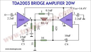
![TDA2003 Bridge Amplifier 20W circuit - Tronicspro]()
TDA2003 Bridge Amplifier 20W circuit - Tronicspro
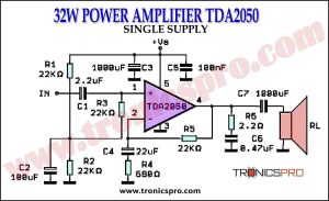
![32W Power Amplifier TDA2050 Single Supply Circuit Diagrm]()
32W Power Amplifier TDA2050 Single Supply