Introduction
A powerful and efficient subwoofer amplifier circuit is essential for audiophiles and enthusiasts looking to enhance their audio experiences. In this article, we will explore the creation of a 100W subwoofer amplifier circuit utilizing not one, but two 2N3773 transistors in the output stage, along with 2N5294, 2N6107, and BC108 transistors. This circuit promises to deliver deep, resonant bass tones that will elevate your audio setup to the next level.
Understanding the 2N3773 Transistor:
Before we dive into the circuit design, it’s crucial to understand the key specifications of the 2N3773 transistor. This power transistor is well-suited for high-power amplification due to its robust characteristics:
Maximum Collector-Base Voltage (Vcb): 160V
Maximum Collector-Emitter Voltage (Vce): 140V
Maximum Collector Current (Ic): 16A
Power Dissipation (Pd): 150W
Gain (hfe): 20-70
Subwoofer Amplifier Circuit Diagram 2N3773
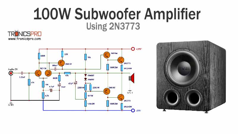
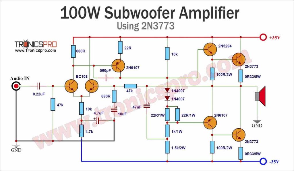
This project can be built using a few basic components. The circuit diagram of this project is shown below.
More Circuit Layouts





Components List of Subwoofer Amplifier Circuit 2N3773
To create our Subwoofer Amplifier Circuit 2N3773 of 100W, we will need the following components:
- 2N3773 Transistor x 2
- 2N5294 Transistor x 1
- 2N6107 Transistor x 2
- BC108 Transistor x 2
- 0.22uF Capacitor x 1
- 4.7uF Capacitor x 1
- 10uF Capacitor x 1
- 560pF Capacitor x 1
- 47uF Capacitor x 1
- 47k Resister x 2
- 10k Resister x 2
- 4.7k Resister x 1
- 680 ohms Resister x 1
- 22 ohms Resister x 1
- 22 ohms 1w Resister x 2
- 1k 1w Resister x 1
- 1.5k 2w Resister x 1
- 100 ohms 2w Resister x 2
- 0.33 ohms 5w Resister x 2
Working Explanation of Subwoofer Amplifier Circuit 2N3773
How the Circuit Works:
Input Stage: The audio input signal is fed into the amplifier circuit through the input terminals. The BC108 transistor amplifies this signal.
Voltage Amplification: The 2N5294 transistor is responsible for the initial voltage amplification stage. It increases the voltage of the signal.
Driver Stage: The 2N6107 transistor is used as a driver to ensure the 2N3773 output transistors receive the necessary current to operate effectively.
Output Stage: The heart of the amplifier lies in the two 2N3773 transistors connected in a push-pull configuration. This configuration allows for efficient amplification of the audio signal, delivering 100W of power to the subwoofer.
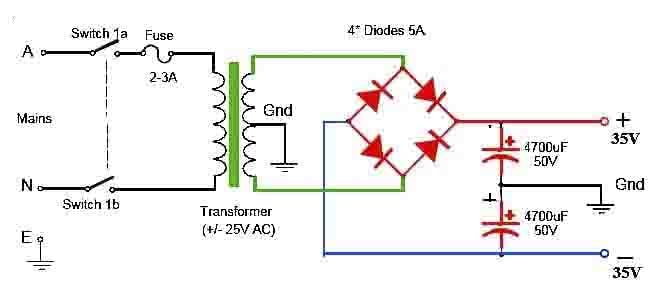
Power Supply: A suitable power supply unit provides the required +/-35V DC voltage to operate the amplifier circuit. Ensure that it meets the voltage and current requirements of the transistors.
Construction and Assembly:
In previous tutorials, we made 800W Amplifier using C5200 A1943, Bass Tone Control Circuit using LM324 Opamp and Subwoofer Amplifier 100W using LM7332. But in this tutorial, we will design a 100 Watt RMS output Subwoofer Amplifier Circuit 2N3773.
- Start by preparing the PCB according to the circuit diagram.
- Solder the transistors, resistors, capacitors, and other components onto the PCB.
- Attach heat sinks to the 2N3773 transistors to dissipate heat efficiently.
- Connect the input and output terminals as per the circuit diagram.
- Ensure proper insulation and safety precautions when connecting the power supply.
Performance and Testing:
After assembling the circuit, it’s essential to test its performance:
- Connect an audio source to the input terminals.
- Gradually increase the volume while monitoring the output.
- Ensure that the subwoofer receives the amplified signal and reproduces the bass frequencies accurately.
- Check for any distortion or overheating issues.
Conclusion
Building a 100W subwoofer amplifier circuit with two 2N3773 transistors in the output stage, along with 2N5294, 2N6107, and BC108 transistors, opens up new possibilities for enhancing your audio system. This circuit, with its powerful amplification capabilities, promises to deliver deep and immersive bass experiences that will elevate your audio setup to a whole new level of performance.
Incorporating the right components, understanding the specifications of the 2N3773 transistor, and following the construction steps outlined in this article will help you create a high-quality subwoofer amplifier circuit using 2N3773 that will impress even the most discerning audiophiles.
More projects, You may like:
- Video Transmitter DIY Homemade FM Radio Transmitter
- Adjustable Power Supply DIY Battery Charger
- 12V-220V 500 Watt inverter DIY Homemade
- 12V-220V H-Bridge Inverter DIY Homemade
- MPPT Solar Charge Controller DIY Homemade
- 18650 battery bank free charge protection module
- D718 B688 Bass Amplifier Homemade DIY
- C5200 Bass Amplifier DIY Homemade with Volume
- DIY LA4440 bass amplifier homemade
- C5200 A1943 TDA2030 Amplifier DIY Homemade
For more project and circuit diagrams, you can go through the Schematics in the main menu where you can find many interesting projects and circuit diagrams like audio amplifier circuits, voltage booster circuit, battery charger circuit and timer circuits etc., which are all beginner circuit projects. Feel free to check them out!

Thank you for visiting the article.


