Introduction
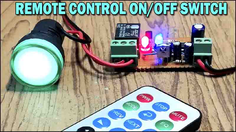
Remote control switches have become an integral part of our daily lives, making it convenient to control appliances and devices from a distance. In this article, we will guide you on how to make a remote control ON-OFF switch using the CD4017 IC, TSOP1838 IR sensor, BC547 and BC557 transistors. These components, when combined, create a simple yet effective remote control switch that can be used to control various devices wirelessly. So, let’s dive in and explore each component in detail.
Introduction to Major Parts
CD4017 IC
The CD4017 is a versatile integrated circuit that can be utilized in various applications, including remote control systems. It is a 16-pin counter/divider IC that can divide the clock frequency by 10. The output of each counter stage changes sequentially with each received clock pulse. The counter stages are connected in a manner that when the first output is active, the remaining are off. Then, with each successive clock pulse, the active output moves to the next stage, while the previous one turns off.
TSOP1838 IR Sensor
The TSOP1838 is an infrared sensor module that enables the remote control switch to receive signals transmitted by an IR remote control. It operates on a specific frequency and has a demodulator to convert the IR signal to a digital output. The TSOP1838 is designed to filter out ambient light, ensuring that only the IR signals are detected. This makes it ideal for applications where precise control is required, such as operating appliances using a remote control.
BC547 Transistor
The BC547 is a general-purpose NPN transistor that can be used in a wide range of electronic circuits. It is commonly used for amplification and switching purposes. The BC547 can handle a maximum continuous collector current of 100 mA, making it suitable for low to medium power applications. It has a high current gain and low saturation voltage, which makes it an excellent choice for the remote control ON-OFF switch circuit.
BC557 Transistor
The BC557 is a complementary PNP transistor to the BC547. It also has a maximum continuous collector current of 100 mA and is often used as a complement to the BC547 in transistor pair configurations. The BC557 offers similar characteristics to the BC547, making them a perfect match for the remote control switch circuit.

Circuit Diagram of Remote Control ON-OFF Switch
This project can be designed using a few basic components. The circuit diagram of this project is shown below.
More Circuit Layouts


Components List of Remote Control ON-OFF Switch
Following is the list of all components used in this project:
- 1X CD4017 IC
- 1X TSOP1838 IR SENSOR
- 1X BC547 TRANSISTOR
- 1X BC557 TRANSISTOR
- 1X 4148 DIODE
- 2X LEDS
- 2X 10uF CAPACITOR
- 1X 22uF CAPACITOR
- 1X 100uF CAPACITOR
- 1X 100 OHM RESISTOR
- 2X 220 OHM RESISTORS
- 4X 10K RESISTOR
- 1X 2 PIN TERMINAL BLOCK
- 1X 3 PIN TERMINAL BLOCK
- 1X 5V RELAY
- 1X PREF BOARD
- JUMPER WIRES
Construction of Remote Control ON-OFF Switch
To construct the remote control ON-OFF switch circuit, connect the CD4017 IC to power and ground, and connect the IR sensor output to the clock input of the IC. The outputs of the CD4017 IC should be connected to the base terminals of the BC547 transistors through appropriate resistors. Finally, connect the emitter terminals of the BC547 to ground and BC557 transistors to the load or device you want to control remotely. Connect rest of all the components according to the circuit diagram provided above.
Once the circuit is wired up correctly, power it up and point an IR remote control towards the TSOP1838 IR sensor. Pressing any button on the remote control will send a specific IR signal that will be received by the TSOP1838 IR sensor. This signal will be accepted by the CD4017 IC, causing it to count and activate the appropriate output pin. The activated output pin will turn on the corresponding BC547 transistor, which will in turn activate the BC557 transistor. The load or device connected to the emitter of the BC557 transistor will then be turned on or off via a 5v relay, depending on the remote control button pressed.
Conclusion of Remote Control ON-OFF Switch
In conclusion, creating a remote control ON-OFF switch using the CD4017 IC, TSOP1838 IR sensor is a fun and practical project. By following the wiring connections and understanding the capabilities of each component, you can construct a reliable and efficient remote control switch. This DIY project allows you to control various devices wirelessly, adding convenience to your daily life. So, gather the necessary components, follow the guidelines provided, and enjoy the benefits of a remote control ON-OFF switch.
More projects, You may like:
- Video Transmitter DIY Homemade FM Radio Transmitter
- Adjustable Power Supply DIY Battery Charger
- 12V-220V 500 Watt inverter DIY Homemade
- 12V-220V H-Bridge Inverter DIY Homemade
- MPPT Solar Charge Controller DIY Homemade
- 18650 battery bank free charge protection module
- D718 B688 Bass Amplifier Homemade DIY
- C5200 Bass Amplifier DIY Homemade with Volume
- DIY LA4440 bass amplifier homemade
- C5200 A1943 TDA2030 Amplifier DIY Homemade
For more project and circuit diagrams, you can go through the Schematics in the main menu where you can find many interesting projects and circuit diagrams like audio amplifier circuits, voltage booster circuit, battery charger circuit and timer circuits etc., which are all beginner circuit projects. Feel free to check them out!
Thanks for visiting the article and watching the video.


