Introduction
Displaying time is an essential part of many electronic applications. One of the coolest projects is making a digital clock with Arduino Nano and 16×2 LCD display. The Arduino is an open-source electronics platform that can be used to work with various sensors, actuators, and other devices. In this article, we will learn how to use an Arduino and a 16×2 LCD display to build a digital clock. This is a diy electronics circuit for beginners which is very simple and easy electronic project.

Circuit Diagram
of How to Make Digital Clock
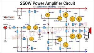
This amplifier can be designed using a few basic components. The circuit diagram of this project is shown below.


More Circuit Layouts


Components List of How to Make Digital Clock
Following is the list of components used in this project:
- 1x ARDUINO NANO
- 1x 16X2 LCD
- 1X 2K2 RESISTOR
- 3x PUSH BUTTON
- 1X 3 PIN TERMINAL BLOCK
- 1X PERF BOARD
- JUMPER WIRES
Gerber Files
Arduino Code File
ZIP Code File
Text Code File
Download Schematic HD
How to Make Digital Clock using Arduino and 16×2 LCD Display:
The clock we are going to make will display the hour, minute, and second in both the 12-hour and 24-hour format. We will also include a feature to adjust the time, so you don’t have to make changes manually. Here is the step by step guide to make a digital clock using Arduino and 16×2 LCD display.
Step 1: Gather the Parts of Digital Clock
Firstly, we need to gather all the parts required to build a digital clock. The complete list of all parts are provided above.
Step 2: Connect the Components
Once you have all the components ready, it’s time to connect them. First, connect the Arduino Nano and the 16×2 Display module with the help of jumpers wires according to the circuit diagram / schematic provided above. Next, attach all push buttons with the Arduino. Finally, attach the power supply and test the circuit.
Step 3: Upload the Code
After connecting all the components, it’s time to upload the code to the Arduino. You can use the Arduino integrated development environment (IDE) to upload the code. The link of the code for this project is already provided in the list of components section. You can download all files and copy and paste the code in the IDE, or you can write the code yourself.
Conclusion:
Making a digital clock using Arduino and 16×2 LCD display is a fun project that anyone with basic knowledge of electronics can create. It’s a great way to learn about sensors, actuators, and other devices that you can use with Arduino. With the help of this article, you can build your own digital clock and learn about the basics of electronics and programming. Have fun making your project!
More projects, You may like:
- Video Transmitter DIY Homemade FM Radio Transmitter
- Adjustable Power Supply DIY Battery Charger
- 12V-220V 500 Watt inverter DIY Homemade
- 12V-220V H-Bridge Inverter DIY Homemade
- MPPT Solar Charge Controller DIY Homemade
- 18650 battery bank free charge protection module
- D718 B688 Bass Amplifier Homemade DIY
- C5200 Bass Amplifier DIY Homemade with Volume
- DIY LA4440 bass amplifier homemade
- C5200 A1943 TDA2030 Amplifier DIY Homemade
You may also like:
 How To Make LED Chaser 8-Channel Multi-Effects
- How To Make Motion Tracking Mobile Mount
- CFL bulb repair at home - tube replacement
- Battery Over Current Protector Circuit Diagram
- How To Make DIY Heart Rate Monitor
- Hand Motion Controlled Light DIY - TRONICSpro
- How To Make 12v-220v DIY Homemade Inverter
- Wireless Water Level Controller DIY Homemade