Introduction
Foldback current limiting is a technique used in voltage regulators to ensure that the maximum current is reduced when the output voltage decreases. This technique is particularly useful when additional current up to 3 A is required, as it helps to prevent the overall dissipation from becoming too high in case of a short-circuit. By incorporating a few additional components into the circuit, foldback regulation can be achieved, providing effective thermal protection and limiting the output current before any damage is done. In this article, we will discuss about foldback current limiting circuit and how the circuit works in detail.
Foldback Current Limiting Circuit Diagram
This project can be designed using a few basic components. The circuit diagram of this project is shown below.

More Circuit Layouts


Components List of Foldback Current Limiting Circuit
Following is the list of all components used in this project:
- 7805 Regulator IC x 1
- 2N2955 Transistor x 1
- BD240C Transistor x 1
- 0.22 ohms / 3W Resister x 1
- 10 ohms Resister x 1
- 6.8 ohms Resister x 1
- 1.5k / 1W Resister x 1
- 100nF Capacitor x 2
Working Explanation of Foldback Current Limiting Circuit
Three-pin voltage regulators like 7805 or 7812 are excellent for normal applications. If currents up to 3 A are required, an additional transistor, such as T2 is used in the following circuit diagram. Adding an additional transistor solution works well, but the overall dissipation can get fairly high in case of a short-circuit. This difficulty can be overcome by foldback regulation. That ensures electronically that the maximum current is reduced (folded back) when the output voltage decreases.
Only a few additional components are needed for foldback regulation. In the given circuit diagram, transistor T1 provides current limiting. As soon as the voltage drop across R2+R3 becomes greater than 0.6-0.7 V, the transistor is switched on, which reduces the base current of T2 to virtually zero. The voltage regulator is more or less on its own, but it has very good thermal protection and limits its output current well before any harm is done. The voltage at which the protection circuits come into operation is the sum of the potentials across R2 and R3.
Resistors R3 and R4 form a voltage divider for the potential across T2. The dissipation in T2 is directly proportional to the collector-emitter voltage, which is thus used here to control the current. In this way, the regulation characteristic is a function of the level of the input voltage.
Conclusion:
In conclusion, foldback current limiting is an effective solution to overcome the high dissipation issue in voltage regulators when higher currents are required. By incorporating additional components like transistors and resistors, the regulator can reduce the maximum current (fold it back) when the output voltage decreases. This ensures better thermal protection and prevents any harm due to excessive current flow. Foldback regulation is a valuable technique for maintaining the stability and efficiency of voltage regulators in various applications.
More projects, You may like:
- Video Transmitter DIY Homemade FM Radio Transmitter
- Adjustable Power Supply DIY Battery Charger
- 12V-220V 500 Watt inverter DIY Homemade
- 12V-220V H-Bridge Inverter DIY Homemade
- MPPT Solar Charge Controller DIY Homemade
- 18650 battery bank free charge protection module
- D718 B688 Bass Amplifier Homemade DIY
- C5200 Bass Amplifier DIY Homemade with Volume
- DIY LA4440 bass amplifier homemade
- C5200 A1943 TDA2030 Amplifier DIY Homemade
For more project and circuit diagrams, you can go through the Schematics in the main menu where you can find many interesting projects and circuit diagrams like audio amplifier circuits, voltage booster circuit, battery charger circuit and timer circuits etc., which are all beginner circuit projects. Feel free to check them out!
Thank you for visiting the article.
You may also like:
![Stepper Motor Control Circuit Diagram]()
Stepper Motor Control Circuit Diagram
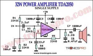
![32W Power Amplifier TDA2050 Single Supply Circuit Diagrm]()
32W Power Amplifier TDA2050 Single Supply
![Automatic Battery Switch Over Circuit Diagram]()
Automatic Battery Switch Over Circuit Diagram
![Op-Amp With Hysteresis Circuit Diagram]()
Op-Amp With Hysteresis Circuit Diagram
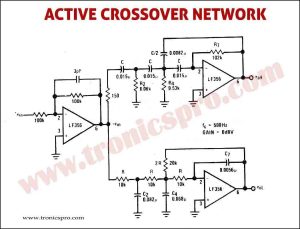
![Active Crossover Network Circuit Diagram]()
Active Crossover Network Circuit Diagram
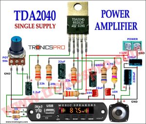
![30W TDA2040 Power Amplifier Circuit Diagram]()
30W TDA2040 Power Amplifier Circuit Diagram
![Light to Frequency Converter Circuit Diagram]()
Light to Frequency Converter Circuit
![Multi Color Led Circuit Diagram]()
Multi Color Led Circuit Diagram