Introduction
The 100W OCL amplifier circuit diagram is a powerful audio amplifier circuit that utilizes the 2N3055 transistor and LM741 operational amplifier (IC) to deliver high-quality sound output. This circuit is widely used in audio systems, music amplifiers, and home theaters, offering an excellent performance for audio enthusiasts.
Specification of 2N3055 Transistor:
The 2N3055 is a highly popular and robust NPN bipolar junction transistor (BJT) widely used in power amplification applications. Here are some key specifications of the 2N3055 transistor:
- Power Dissipation (Pd): Up to 115 Watts.
- Collector-Base Voltage (VCBO): 100 Volts.
- Collector-Emitter Voltage (VCEO): 60 Volts.
- Collector Current (IC): 15 Amperes.
- DC Current Gain (hFE): 20 to 70.
- Transition Frequency (fT): 2.5 MHz.
Specification of LM741 IC:
The LM741 is a popular operational amplifier (op-amp) IC that offers high-performance signal amplification. Here are some key specifications of the LM741 IC:
- Supply Voltage (VCC): ±15 Volts.
- Input Offset Voltage: 2 mV.
- Input Bias Current: 80 nA.
- Input Offset Current: 20 nA.
- Gain Bandwidth Product: 1 MHz.
- Slew Rate: 0.5 V/μs.
OCL Amplifier Circuit Diagram
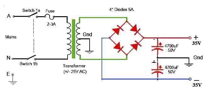
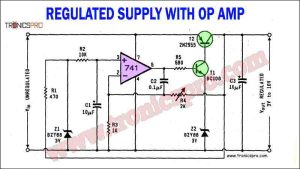
This project can be built using a few basic components. The circuit diagram of this project is shown below.
More Circuit Layouts


Components List of OCL Amplifier Circuit Diagram
Following is the list of all components used in this project:
- 2N3055 or TIP3055 Transistor x 1
- MJ2955 or TIP2955 Transistor x 1
- BD139 or 2N3053(TO-39) Transistor x 1
- BD140 or 2N4037(TO-39) Transistor x 1
- LM741 or LF351, TL071 Op-Amp IC x 1
- 1N5245 15V 0.5W Zener Diode x 2
- 1N4148 Diode x 2
- 50K Potentiometer x 1
- 1K Potentiometer x 1
- 10uF 16V Electrolytic Capacitor x 1
- 47uF 25V Electrolytic Capacitor x 2
- 100uF 16V Electrolytic Capacitor x 1
Explanation of OCL Amplifier Circuit Diagram
Circuit Diagram of the 100W OCL Amplifier:
The circuit diagram consists of the 2N3055 transistor and LM741 IC as the main components. The input signal is first amplified by the LM741 operational amplifier and then fed to the power transistor. Here is a brief description of the circuit diagram:
- Input Stage: The audio input signal is connected to the non-inverting input of the LM741 op-amp through a coupling capacitor for DC blocking. The inverting input is connected to ground.
- Amplification Stage: The LM741 operational amplifier amplifies the input signal and provides a high voltage gain. The gain can be adjusted by using feedback resistors.
- Output Stage: The amplified signal is then fed to the base of the 2N3055 transistor via a coupling capacitor. The transistor amplifies the signal further and drives the speaker or load connected to the collector-emitter path.
Conclusion
The 100W OCL amplifier circuit utilizing the 2N3055 transistor and LM741 IC is a reliable and powerful audio amplifier that can deliver high-quality sound output. By combining the specifications and characteristics of these components, this circuit provides excellent performance for various audio applications. Whether you are a music enthusiast or a professional sound engineer, this amplifier circuit will surely satisfy your audio amplification needs.
More projects, You may like:
- 200W 4-Channel TDA7560 Amplifier Circuitr
- Variable Power Supply 0-30V_10A Circuit Diagram
- 2N3055 MJ2955 Class-AB Stereo Amplifier Circuit
- C5200 A1943 amplifier DIY homemade
For more project and circuit diagrams, you can go through the Schematics in the main menu where you can find many interesting projects and circuit diagrams like audio amplifier circuits, voltage booster circuit and timer circuits etc., which are all beginner circuit projects. Feel free to check them out!


Thank you for visiting the article.


Nice to learn off these circuits.