

Introduction

In the world of electronics, amplifiers hold a significant place. They are widely used in audio systems, musical instruments, and various other applications, where amplification of signals is required. One such powerful amplifier circuit is the 100W Amplifier Circuit Diagram, which utilizes dual 2SC5200 transistors in the output section, TIP41 & TIP42 transistors in the driver section, and 2SA1015 transistors in the preamplifier section. In this article, we will dive into the details of this circuit, its working principle, and specifications of the transistors used.
Transistor Specifications:
- 2SC5200 Transistor:
- Maximum Collector Current: 15A
- Maximum Power Dissipation: 150W
- Maximum Voltage: 230V
- Transition Frequency: 15MHz
- Gain: 55-70
- TIP41 Transistor:
- Maximum Collector Current: 6A
- Maximum Power Dissipation: 65W
- Maximum Voltage: 65V
- Transition Frequency: 3MHz
- Gain: 15-75
- TIP42 Transistor:
- Maximum Collector Current: 6A
- Maximum Power Dissipation: 65W
- Maximum Voltage: 65V
- Transition Frequency: 3MHz
- Gain: 15-75
100W Amplifier Circuit Diagram using dual 2SC5200
This project can be built using a few basic components. The circuit diagram of this project is shown below.

±50V Power Supply Circuit Diagram

Caution: Website contains information on high voltage circuits. Proceed at your own risk, ensuring proper knowledge and precautionary measures to prevent electric shock or injury.
More Circuit Layouts


Components List of 100W Amplifier Circuit using 2SC5200
Following is the list of all components used in this project:
- Transistors:
- 2SC5200 Transistor x 2
- TIP41 Transistor x 1
- TIP42 Transistor x 2
- 2SA1015 Transistor x 2
- 2SC2229 Transistor x 2
Resisters: - 22k Resister x 1
- 3.3k Resister x 2
- 33k Resister x 1
- 4.7k/2W Resister x 1
- 1k Resister x 1
- 68k Resister x 1
- 10k Resister x 1
- 150Ω Resister x 3
- 33Ω Resister x 1
- 100Ω/1W Resister x 2
- 0.47Ω/5W Resister x 2
- 10Ω/2W Resister x 1
- 10Ω/1W Resister x 1
Capacitors: - 2.2µF Capacitor x 1
- 100µF Capacitor x 2
- 10µF Capacitor x 2
- 1nF Capacitor x 2
- 100nF Capacitor x 1
Miscellaneous: - 24V Zener Diode x 1
- 1N4007 Diode x 3
- ±50V Power Supply
Explanation of 100W Amplifier Circuit Diagram using dual 2SC5200
The 100W Amplifier Circuit Diagram using 2SC5200 transistors employs a combination of high-quality transistors to provide a robust and efficient amplification process. The circuit diagram consists of three main sections: the preamplifier section, the driver section, and the output section.
In the preamplifier section, 2SA1015 transistors are utilized. These transistors are known for their low noise and high gain characteristics, which ensures that the input signals are amplified accurately without any distortion. The preamplifier section enhances the weak input signals and prepares them for further amplification.
Moving on to the driver section, TIP41 and TIP42 transistors are incorporated. These transistors are widely known for their high power handling capability and excellent driving capability. They efficiently drive the output transistors by providing the required current amplification, thus enabling them to amplify the signals to a much higher power.
Finally, the output section of this circuit employs dual 2SC5200 transistors. These transistors have excellent power handling capabilities and are known for their high current gain characteristics. They work together to provide a maximum power output of 100W. This section plays a crucial role in amplifying the signals from the driver section to a level suitable for output devices such as speakers or any other output source.
Conclusion
The 100W Amplifier Circuit Diagram with its dual 2SC5200 transistors in the output section, TIP41 & TIP42 transistors in the driver section, and 2SA1015 transistors in the preamplifier section provides a powerful and reliable solution for amplifying audio signals. This circuit offers a high power output of 100W while ensuring minimal distortion and noise. The specifications of the transistors used in this circuit make them perfect for their respective sections, providing efficient amplification and driving capabilities. This amplifier circuit will undoubtedly enhance the audio experience in various applications, making it an ideal choice for audio enthusiasts.
More projects, You may like:
- Video Transmitter DIY Homemade FM Radio Transmitter
- Adjustable Power Supply DIY Battery Charger
- 12V-220V 500 Watt inverter DIY Homemade
- MPPT Solar Charge Controller DIY Homemade
- DIY LA4440 bass amplifier homemade
For more project and circuit diagrams, you can go through the Schematics in the main menu where you can find many interesting projects and circuit diagrams like audio amplifier circuits, voltage booster circuit, and timer circuits etc. Feel free to check them out!

Thank you for visiting the article.
You may also like:
![Subwoofer Amplifier Circuit using TL072 & TDA1521 IC]()
Subwoofer Amplifier Circuit Diagram using TL072 & TDA1521 IC
![TDA7294 High-Efficiency Power Amplifier Circuit]()
TDA7294 High-Efficiency Power Amplifier Circuit
![200W Power Amplifier Circuit using 2SD1047 & 2SB817 Transistors]()
200W Amplifier Circuit Diagram using 2SD1047 & 2SB817 Transistors
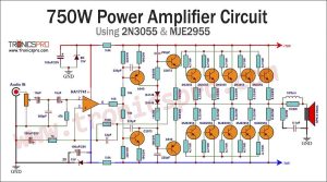
![750W Power Amplifier Circuit Diagram using 2N3055, MJE2955]()
750W Power Amplifier Circuit Diagram using 2N3055 & MJE2955
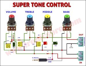
![Bass Tone Control Circuit Diagram]()
Bass Tone Control Circuit Diagram - TRONICSpro
![1000W Power Amplifier Circuit Diagram using 2SC5200 & 2SA1943 Transistors]()
1000W Power Amplifier Circuit Diagram using 2SC5200 & 2SA1943 Transistors
![13003 DIY Bass Amplifier Circuit Diagram]()
13003 DIY Bass Amplifier Circuit Diagram
![100W Bass Amplifier Circuit using 2N3055 & LM3900]()
Bass Amplifier Circuit Diagram using 2N3055 & LM3900 - 100W Single Supply


thanks i built this amplifier, and it has worked perfectly. thanks