Introduction
Amplifiers lie at the heart of modern audio systems, elevating sound signals to create immersive experiences. Among these, the 100W amplifier circuit diagram using 2N3055 and 2N2955 transistors emerges as a powerful solution for audio enthusiasts seeking enhanced performance. This article wil explore the intricacies of this circuit, shedding light on its design, components, and the impressive capabilities of the transistors involved.
The Anatomy of the 100W Amplifier Circuit:
At its core, an amplifier intensifies the strength of an electrical signal without altering its essential characteristics. The 100W amplifier circuit diagram harnesses the capabilities of 2N3055 and 2N2955 transistors to deliver remarkable power output. These transistors, renowned for their robustness and efficiency, play a pivotal role in ensuring accurate signal reproduction and minimized distortion.
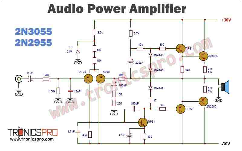
Circuit Diagram of 100W Amplifier Circuit Diagram
This project can be designed using a few basic components. The circuit diagram of this project is shown below.
More Circuit Layouts


Components List of 100W Amplifier Circuit Diagram
Following is the list of all components used in this project:
- 2N3055 Transistor x 1
- MJ2955 Transistor x 1
- TIP31 Transistor x 2
- TIP32 Transistor x 1
- A798 Transistor x 2
- 0.5 ohm 5W Resister x 2
- 390 ohms Resister x 4
- 47 ohms Resister x 1
- 2.7k Resister x 1
- 10k Resister x 3
- 39k Resister x 1
- 100 ohms Resister x 1
- 220 ohms Resister x 1
- 3.9k Resister x 1
- 4.7k Resister x 1
- 100k Resister x 1
- 22uF Capacitor x 1
- 100uf Capacitor x 1
- 220uF Capacitor x 1
- 47uF Capacitor x 1
- 1.2nF Capacitor x 1
- 4.7nF Capacitor x 1
- 100pF Capacitor x 1
- 1N4148 Diode x 2
- ZD 24v Zener Diode x 1
Working Explanation of 100W Amplifier Circuit Diagram
Components and Connections:
Assembling the 100W amplifier circuit diagram necessitates a selection of critical components, each contributing to the circuit’s overall functionality. Resistors, capacitors, and transformers collaborate harmoniously, serving distinct purposes. The judicious arrangement of these elements guarantees signal amplification while maintaining fidelity.
Transistor Specifications:
Let’s dive into the specifications of the transistors that propel this circuit’s prowess:
2N3055 Transistor:
Maximum Collector Current (Ic): 15A
Power Dissipation (Pd): 115W
Collector-Emitter Voltage (Vceo): 60V
Gain (hFE): 20-70
MJ2955 Transistor:
Maximum Collector Current (Ic): 15A
Power Dissipation (Pd): 115W
Collector-Emitter Voltage (Vceo): 60V
Gain (hFE): 20-70
TIP31 Transistor:
Maximum Collector Current (Ic): 3A
Power Dissipation (Pd): 40W
Collector-Emitter Voltage (Vceo): 40V
Gain (hFE): 10-50
TIP32 Transistor:
Maximum Collector Current (Ic): 3A
Power Dissipation (Pd): 40W
Collector-Emitter Voltage (Vceo): 40V
Gain (hFE): 25-75
A708 Transistor:
Maximum Collector Current (Ic): 4A
Power Dissipation (Pd): 40W
Collector-Emitter Voltage (Vceo): 60V
Gain (hFE): 40-160
Performance and Sound Quality:
The 100W amplifier circuit diagram showcases its prowess by delivering substantial power output, driving speakers with finesse. The judicious pairing of 2N3055 and 2N2955 transistors ensures efficient energy conversion and excellent linearity, resulting in a sonic experience characterized by clarity and depth.
Building and Testing:
Embarking on the construction journey involves meticulous assembly of components and adherence to the circuit diagram. Rigorous testing and optimization are imperative to ensure optimal performance. The troubleshooting process is equally crucial, addressing potential challenges and guaranteeing a seamless outcome.
Conclusion:
The 100W amplifier circuit diagram employing 2N3055 and 2N2955 transistors stands as a testament to the harmony between innovation and audio technology. Its design intricacies, coupled with the exceptional specifications of the involved transistors, facilitate an audio experience that resonates with precision and power. As technology evolves, this circuit remains a cornerstone for audio enthusiasts, exemplifying the art of sound amplification at its finest
More projects, You may like:
- Video Transmitter DIY Homemade FM Radio Transmitter
- Adjustable Power Supply DIY Battery Charger
- 12V-220V 500 Watt inverter DIY Homemade
- 12V-220V H-Bridge Inverter DIY Homemade
- MPPT Solar Charge Controller DIY Homemade
- 18650 battery bank free charge protection module
- D718 B688 Bass Amplifier Homemade DIY
- C5200 Bass Amplifier DIY Homemade with Volume
- DIY LA4440 bass amplifier homemade
- C5200 A1943 TDA2030 Amplifier DIY Homemade
For more project and circuit diagrams, you can go through the Schematics in the main menu where you can find many interesting projects and circuit diagrams like audio amplifier circuits, voltage booster circuit, battery charger circuit and timer circuits etc., which are all beginner circuit projects. Feel free to check them out!

Thank you for visiting the article.


