Introduction
Power amplifiers are crucial components in audio systems, responsible for boosting the amplitude of electrical signals to drive speakers or other devices. When it comes to high-power applications, the 1000W power amplifier circuit diagram, using the 2SC5200 and 2SA1943 transistors, is a popular choice among audiophiles and professionals alike. In this article, we will present the circuit diagram, discuss the specifications of these transistors, and highlight the features and benefits of this amplifier design.
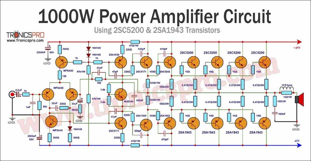
1000W Power Amplifier Circuit Diagram using 2SC5200 & 2SA1943
The 1000W power amplifier circuit schematic utilizing the 2SC5200 and 2SA1943 transistors is a robust design capable of delivering high-quality audio output. This amplifier operates on a ±45V to 75V DC power supply and employs a complementary pair of transistors for each channel. The circuit diagram ensures the accurate reproduction of sound by providing substantial power to the speakers.
This project can be built using a few basic components. The circuit diagram of this project is shown below.
Caution: Website contains information on high voltage circuits. Proceed at your own risk, ensuring proper knowledge and precautionary measures to prevent electric shock or injury.
More Circuit Layouts



Components List of 1000W Power Amplifier Circuit Diagram
Following is the list of all components used in this project:
- 2SC5200 Transistors x 4
- 2SA1943 Transistors x 4
- 2SC5242 Transistors x 1
- 2SA1962 Transistors x 1
- 2SC5171 Transistors x 2
- 2SA1930 Transistors x 2
- MJE340 Transistors x 1
- MPSA92 Transistors x 3
- MPSA42 Transistors x 1
- 1N4148 Diode x 2
Explanation of 1000W Power Amplifier Circuit Diagram
Specifications of 2SC5200 Transistor
The 2SC5200 is an epitaxial silicon NPN transistor widely used for high-power amplifier designs. This transistor offers exceptional linearity, low distortion, and high efficiency. Its key specifications include a maximum collector-emitter voltage of 230V, a maximum collector current of 15A, and a power dissipation rating of 150W. With a transition frequency of 30MHz, the 2SC5200 transistor can handle high-frequency signals with ease, making it an ideal choice for power amplifiers.
Specifications of 2SA1943 Transistor
The 2SA1943 is a complementary PNP transistor to the 2SC5200 and is designed to work in tandem with it. This transistor also boasts excellent linearity and low distortion characteristics. It has a maximum collector-emitter voltage rating of 230V, a maximum collector current of 15A, and a power dissipation of 150W. With a transition frequency of 30MHz, it complements the 2SC5200 transistor effectively, ensuring a balanced and distortion-free amplification.
Features and Benefits of the 1000W Power Amplifier
- High Power Output: With a power rating of 1000W, this amplifier can deliver a substantial amount of power, making it suitable for various applications, including home theaters, live sound reinforcement systems, and recording studios.
- Low Distortion: The 2SC5200 and 2SA1943 transistors used in this design offer low distortion and high linearity, resulting in accurate and faithful audio reproduction.
- Wide Frequency Response: Thanks to the high transition frequency of 30MHz, this amplifier can handle a wide range of frequencies, ensuring clear and detailed sound reproduction across the audible spectrum.
- Robust Construction: The circuit design incorporates efficient cooling mechanisms and protection circuits to prevent thermal runaway and ensure long-term reliability even during demanding operating conditions.
- Versatility: The 1000W power amplifier circuit can be easily modified or adapted to suit different requirements, such as bridging multiple amplifiers for even higher power output or connecting to different speaker impedance loads.
Conclusion
In conclusion, the 1000W power amplifier circuit using the 2SC5200 and 2SA1943 transistors offers outstanding performance, power, and versatility. This amplifier design provides a reliable solution for high-power audio applications, delivering clear and accurate sound reproduction. With its low distortion, wide frequency response, and robust construction, it is an excellent choice for audiophiles, professionals, and enthusiasts seeking a high-quality power amplifier for their audio systems.
More projects, You may like:
- Video Transmitter DIY Homemade FM Radio Transmitter
- Adjustable Power Supply DIY Battery Charger
- 12V-220V 500 Watt inverter DIY Homemade
- 12V-220V H-Bridge Inverter DIY Homemade
- MPPT Solar Charge Controller DIY Homemade
- 18650 battery bank free charge protection module
- D718 B688 Bass Amplifier Homemade DIY
- C5200 Bass Amplifier DIY Homemade with Volume
- DIY LA4440 bass amplifier homemade
- C5200 A1943 TDA2030 Amplifier DIY Homemade
For more project and circuit diagrams, you can go through the Schematics in the main menu where you can find many interesting projects and circuit diagrams like audio amplifier circuits, voltage booster circuit, battery charger circuit and timer circuits etc., which are all beginner circuit projects. Feel free to check them out!

Thank you for visiting the article.


