The tone controls on sound mixers are regularly known as equalization controls. Tone Controller permits listeners to alter sound to their liking. It additionally allows them to catch up on recording deficiencies, listening to impairments, room acoustics or shortcomings with playback equipment.
The circuit is built with only ceramic capacitors and resisters. The provides better and clear sound. It gives nice sound quality with heavy bass and full control over sound.
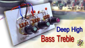
In the following video Tone Control Volume Circuit, I am showing, a way to make an extremely powerful ultra bass Tone Controller of Volume, Bass, Treble & Middle. There are 3 potentiometers used and no transistor or IC is used in this circuit.

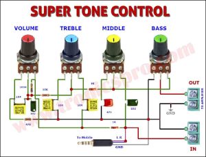
Circuit Diagram
Below is the Circuit Diagram of Tone Control Volume Circuit with volume, bass, treble and middle. It uses minimum components and its ideal for beginners and learners.
If you want to download the circuit diagram, just click on the image and then click the download button. to download the circuit diagram into your computer for future use.

More Circuit Layouts


List of Components used in Tone Control Volume Circuit
- 104J Capacitor x 3
- .001J (473) Capacitor x 1
- 2A102J Capacitor x 2
- 470 Ohms Resister x 1
- 1k Ohms Resister x 2
- 10k Ohms Resister x 1
- 100k Ohms Resistor x 1
- 50k Potentiometer Single Pole x 4
Development images
used in Tone Control Volume Circuit
Step-1
First fix four potentiometer 50k value in series on a card board. Then take one 104J capacitor and fix its its two leg to pin.1 and pin.2. Take one 102J ceramic capacitor and fix its both legs to pin-2 and pin-3.

Step-2
Now solder one 100k resister to pin-2 and pin-3 of first left pot. Take another resister of 1k value and solder its one leg to pin-2 of first left pot and the other leg to pin-2 (center pin) of second left pot.

Step-3
Now take one 104J capacitors and solder its one leg to pin-1 of second left pot. And take one more 104J capacitor and solder its one leg to pin-3 of the same pot.

Step-4
Take one 473 ceramic capacitor and solder its one leg to pin-1 of third left pot.

Step-5
Connect & solder the other leg of 473 ceramic capacitor with 104J which was solder to pin-1 of second left pot.

Step-6
Join or solder one another 102J ceramic capacitor with pin-3 of third left pot. Now solder the other leg of it, to a new 1k resister. Now the other leg of 1k resister solder with 104J capacitor which was joint with pin-3 of second left pot.

Step-7

Step-8

Step-9

Step-10

Step-11

Step-12

Step-13

Step-14

Step-15

Step-16

Step-17

Step-18

Thanks for watching & visiting the site. Please share it with your friends. Thank you.Shortcode