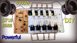
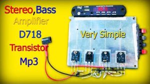
Following is the circuit of D718 B688 Bass Amplifier. This circuit diagram uses 4 nos of D718 NPN transistors and 4 nos of B688 PNP transistors with very few components. All the images shown here are clickable to look at the associated mission motion pictures or downloading the circuit diagrams.
Take a be aware which you need to use aluminium heat sink with a fan (if posible) to save you over heating at the transistors. These circuits require symmetrical/twin and unmarried polarity strength deliver. The capacitors of strength deliver kind is electrolytic capacitor.

Circuit diagram
used in D718 B688 Bass Amplifier
Following is the circuit diagram of D718 B688 Bass Amplifier. This circuit diagram uses minimum components and its very easy to assemble for beginners and students.
NOTE: THE BOTTOM CONNECTION OF SPEAKER WILL GO TO COLLECTOR OF B688, NOT TO EMITTER.
More Circuit Layouts


Development Images
used in D718 B688 Bass Amplifier
Step-1
First take a large and solid heat sink and tighten 4 nos of B688 transistors side by side with mica (rubber insulation). Join pin-1 of all transistors and solder with a piece of naked wire. Then repeat the same practice with pin-2 and pin-3 respectively.

Step-2
Tighten all 4 nos of D718 transistors side by side and repeat the practice same as above.

Step-3
Take a 100k / 1 watt resister and solder with Pin-3 (emitter) of B688 transister’s set and Pin-1 (base) of D718 transistor’s set.

Step-4
Connect Pin-1 (base) of B688 transistor’s set with Pin-2 (collector) of D718 transistor’s set.

Step-5

Step-6

Step-7

Step-8

Step-9

Step-10

Step-11

Step-12

Step-13
List of components
- Transisters:
- D718 transistor x 5
- B688 transistor x 5
- Capacitors:
- 10uf / 50v capacitor x 1
- 104 / 250v capacitor x 1
- Resisters:
- 0.33 ohms / 5 watts resister x 2
- 100k / 1 Watt resister x 1
- Miscellaneous:
- 12 volts single power supply
- 12 dc socket
- Audio input jack
- Large heat sink x 2
- Speakers 4 ohms.
Thank you for visiting the article. Please share it with your friends and enjoy the project. Thank you.


Bad project. Fake circuit.
12v+ connect with speaker (+). ✓✓✓✓✓
GND connect with speaker (-). !?!?!?!?!?
Voila! Same buzzing noise as this useless circuit
Please see the note above the diagram. Thanks.