I will show you how to convert a 7.0 Ah battery into a powerful battery bank mobile charger with six USB ports. Battery charging process is not shown here. You will have to make arrangement separately. This mobile charging device can re-charge six mobiles at a time with maximum amperage required. You should always be safe and do it at your own risk.

Development images
used in battery bank mobile charger
Basic components:
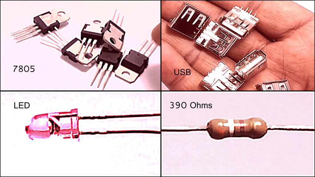
Following image shows the basic components required to build this project. In the top left image, there are six LM7805 positive voltage regulator ic 5 volts / 1.5A. Top right is showing six pieces of USB female sockets. Bottom right has one 390 ohms resister and the last image has one LED of any desired color. I designed this battery bank for six USB ports at a time. You can modify it as per your own requirement.
More Circuit Layouts


This is 12 volts 7.0 Ah (7000 mAh) battery, which is the main mandatory item of this project. You can use any smaller battery to fulfill your need.

Installing components:
Take any kind of heat sink to fit all six ICs on it. I used two small as available but you can use all separate for each IC or one large heat sink. Heat sink(s) should be large enough for proper heat dissipation.

Stick all heat sinks on the surface of the battery and glue them tightly. Make sure there must be enough distance between the battery terminals and the heat sink to prevent short circuit. Because all ICs are directly connected with the heat sink which will be connected with the negative voltage. So it must be away from positive terminal of the battery.

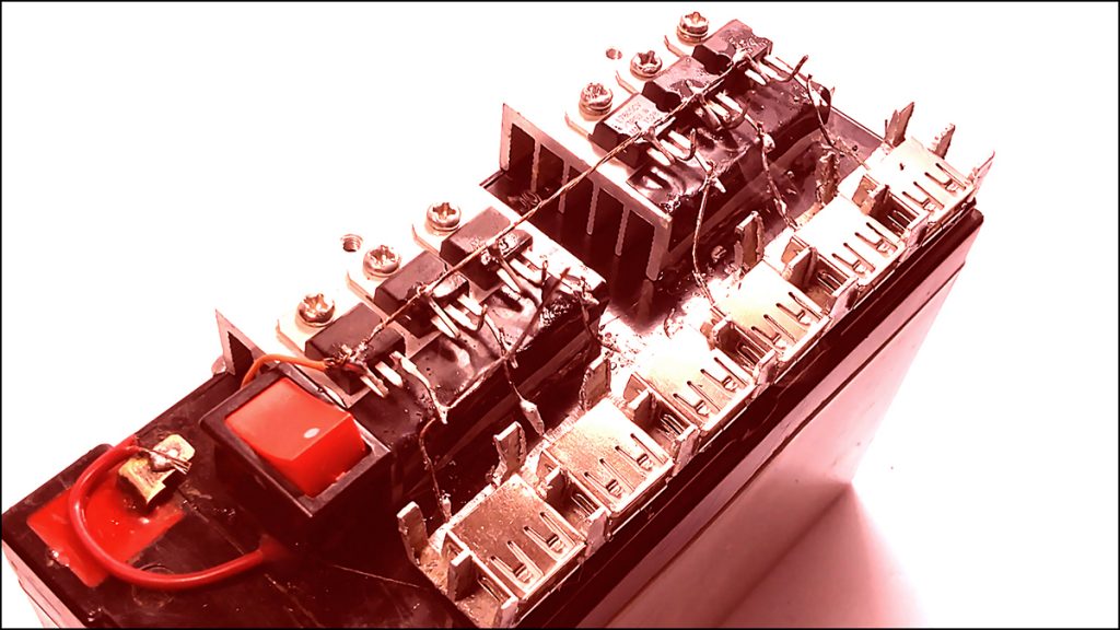
Take one piece of plastic, wood or metal and make six portions with equal distance. I used here a piece of aluminum channel after cutting with mini hand grinder. Glue all USB female sockets in bottom and stick with the plate.

It should look same as in the following image, if you are making in the same way.

Use one 12 volts on/off switch. Solder two pieces of wires and stick in any safe place. I fixed it between battery terminals and the heat sink.

Soldering components:
One wire coming from the switch, solder it with the positive terminal of the battery. Be sure the switch should in OFF stat to avoid running voltage through it during assembling. Also solder the other wire of the switch to pin.1 of IC for input voltage. Now join pin.1 of all six ICs together to supply positive voltage from the on/off switch.

Now take small piece of wire and solder its one end to pin.3 for 5 volts output and the other end to right pin of USB female socket.

Repeat the above step for other five ICs to connect all USB female sockets separately.
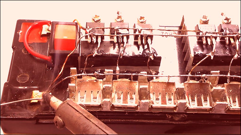
Following image shows the negative connections for all ICs and all USB female sockets. Take two large naked wires and connect all center pins of ICs and all left pins of USB female sockets. And then both wires solder with the negative terminal of the battery.
Connect and solder the 390 ohms resister’s one leg with the long positive leg of indicator LED. And solder the other leg of 390 ohms resister to pin.1 of any IC.

Now solder the negative small leg of indicator LED to the negative terminal of the battery. The LED should glow at this stage if the on/off switch is in ON state.

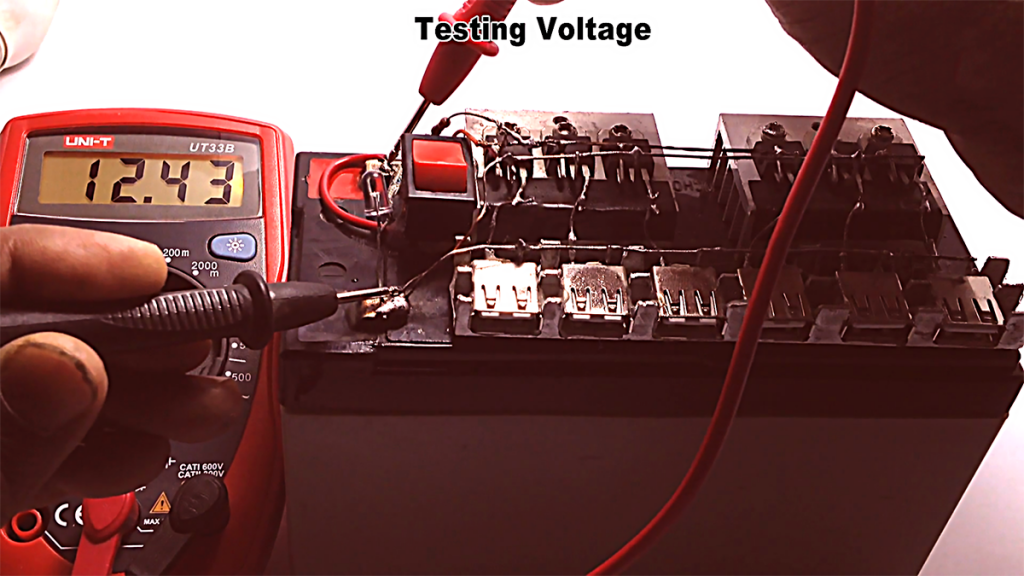
The volt meter is showing the battery voltage from its terminals.
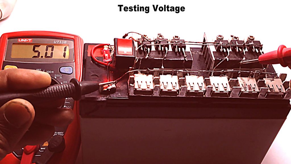
Volt meter is now showing the output voltage of the IC going to USB female socket for mobile charging.
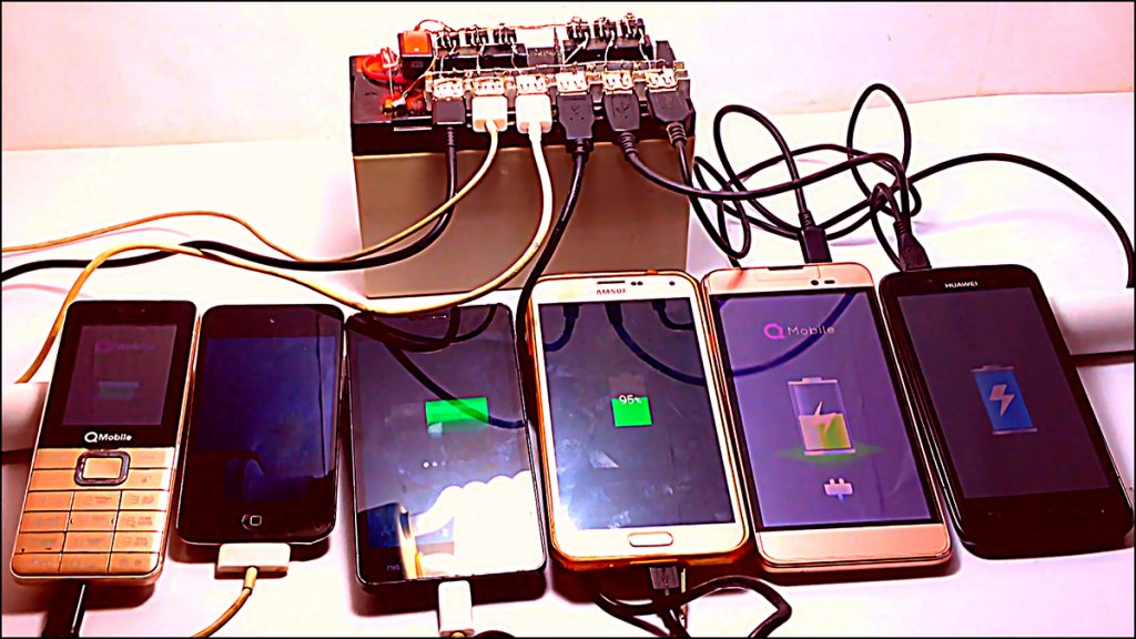
In the below image we can see six mobiles are connected with all six USB female sockets and charging at a time.
Thanks for visiting the site and enjoy the project. Please share it with your friends. Thank you.


