Introduction
When it comes to enhancing the bass quality in audio systems, a dedicated subwoofer amplifier circuit is essential. In this article, we will discuss a powerful and efficient BASS subwoofer amplifier circuit diagram that utilizes MJ11016 and MJ11015, BD139, BC546, and BC556 transistors. These transistors are known for their high power handling capabilities, making them ideal for driving subwoofers effectively.
MJ11016 and MJ11015 Transistors:
The MJ11016 and MJ11015 transistors are complementary power transistors that can handle high power and voltage ratings. These transistors are commonly used in audio amplifiers, including subwoofer circuits, due to their ability to deliver high current to the load. The MJ11016 is an NPN transistor, while the MJ11015 is a PNP transistor. By using both of these transistors, the circuit ensures efficient power delivery with low distortion.
BD139, BC546, and BC526 Transistors:
Apart from the MJ11016 and MJ11015 transistors, other transistors such as BD139, BC546, and BC556 are also used in the subwoofer amplifier circuit diagram. The BD139 is an NPN transistor commonly used as a driver transistor, providing sufficient current gain for the power transistors. The BC546 and BC556 are both NPN and PNP transistors that serve as pre-amplifier transistors, amplifying the input signal before it reaches the power transistors. These transistors contribute to the overall performance and functionality of the subwoofer amplifier circuit.
Specifications of transistors used:
MJ11016 Transistor:
- Type: NPN
- Collector Current: 30A
- Voltage Ratings: 250V
- Power Dissipation: 125W
- Package: TO-3
MJ11015 Transistor:
- Type: PNP
- Collector Current: 30A
- Voltage Ratings: 250V
- Power Dissipation: 125W
- Package: TO-3
BD139 Transistor:
- Type: NPN
- Collector Current: 1.5A
- Voltage Ratings: 80V
- Power Dissipation: 8W
- Package: TO-126
BC546 Transistor:
- Type: NPN
- Collector Current: 100mA
- Voltage Ratings: 65V
- Power Dissipation: 500mW
- Package: TO-92
BASS Subwoofer Amplifier Circuit Diagram
This project can be built using a few basic components. The circuit diagram of this project is shown below.
Caution: Website contains information on high voltage circuits. Proceed at your own risk, ensuring proper knowledge and precautionary measures to prevent electric shock or injury.
More Circuit Layouts









Components List of BASS Subwoofer Amplifier Circuit Diagram
Following is the list of all components used in this project:
Transistors:
- MJ11016 NPN Darlington Transistor x 1
- MJ11015 PNP Darlington Transistor x 1
- BD139 NPN Transistors x 2
- BC546 NPN Transistors x 2
- BC556 PNP Transistor x 1
Resisters:
- 0.47/5W Resistor x 2
- 470R Resistors x 2
- 2K Trimmer x 1
- 4K7 Resistors x 2
- 220R Resistor x 1
- 2K2 Resistor x 2
- 50K Trimmer x 1
- 68K Resistor x 3
- 680K Resistor x 1
- 220K Resistor x 1
- 33K Resistor x 1
- 5K6 Resistor x 1
- 330R Resistors x 2
- 47K Resistor x 1
- 18K Resistor x 1
- 4K7 Resistor x 1
- 1K Resistor x 1
- 1K5 Resistor x 1
- 100K Resistors x 3
- 10K Resistor x 1
- 10K Potentiometer x 2
Capacitors:
- 47µF 63V Electrolytic Capacitors x 5
- 100µF 25V Electrolytic Capacitor x 1
- 1000µF 50V Electrolytic Capacitor x 1
- 2200µF 63V Electrolytic Capacitor x 1
- 10µF 63V Electrolytic Capacitors x 5
- 220µF 63V Electrolytic Capacitor x 1
- 220nF 63V Polyester Capacitor x 1
- 470nF 63V Polyester Capacitor x 1
- 100nF 63V Polyester Capacitor x 1
- 47pF 63V Ceramic Capacitor x 1
- 33pF 63V Ceramic Capacitor x 1
- SPST Switch x 1
Explanation of BASS Subwoofer Amplifier Circuit Diagram
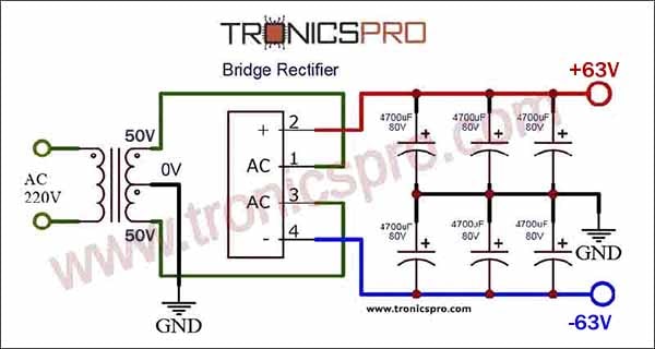
To implement the BASS subwoofer amplifier circuit, you will need the following components: MJ11016, MJ11015, BD139, BC546, BC556 transistors, resistors, capacitors, and power supply.
The circuit diagram consists of input stages, driver stages, and output stages. The input signal is amplified by the pre-amplifier transistors BC546 and BC556. The amplified signal is then fed to the driver transistor BD139, which further amplifies the signal and drives the power transistors MJ11016 and MJ11015. These power transistors deliver a high current to the subwoofer, resulting in crisp and powerful bass output.
Conclusion
In conclusion, the BASS subwoofer amplifier circuit diagram utilizing MJ11016 and MJ11015 transistors is an excellent choice for those seeking to enhance the bass quality in their audio systems. The incorporation of BD139, BC546, and BC556 transistors ensures efficient amplification of the input signal and accurate power delivery to the subwoofer. With its high power handling capabilities and low distortion characteristics, this circuit diagram guarantees an immersive and enjoyable audio experience with deep and dynamic bass.
More projects, You may like:
- Video Transmitter DIY Homemade FM Radio Transmitter
- Adjustable Power Supply DIY Battery Charger
- 12V-220V 500 Watt inverter DIY Homemade
- MPPT Solar Charge Controller DIY Homemade
- DIY LA4440 bass amplifier homemade
For more project and circuit diagrams, you can go through the Schematics in the main menu where you can find many interesting projects and circuit diagrams like audio amplifier circuits, voltage booster circuit, battery charger circuit and timer circuits etc., which are all beginner circuit projects. Feel free to check them out!


Thank you for visiting the article.


