
Introduction
In the world of audio amplification, having a high-quality power amplifier is essential for producing clear and crisp sound. One popular choice for building a powerful audio amplifier is using 2SC5200 & 2SA1943 transistors in the output section. These transistors are known for their high power and excellent linearity, making them ideal for audio applications. In this article, we will discuss a 600W audio power amplifier circuit diagram that utilizes 2SC5200 & 2SA1943 transistors in the output section, along with other transistors like MJE340, MJE350, MPSA42, MPSA92 in the driver section and 2N5551 in the preamplifier section.
The use of these high-quality components ensures that the audio output is not only powerful but also distortion-free. With a power output of 600W, this amplifier is suitable for large gatherings and events where high-quality sound is a must.
Specifications of Transistors Used:
2SC5200:
- Maximum Collector Current: 15A
- Maximum Collector-Emitter Voltage: 230V
- Maximum Power Dissipation: 150W
2SA1943:
- Maximum Collector Current: 15A
- Maximum Collector-Emitter Voltage: 230V
- Maximum Power Dissipation: 150W
MJE340:
- Maximum Collector Current: 0.5A
- Maximum Collector-Emitter Voltage: 300V
- Maximum Power Dissipation: 0.5W
MJE350:
- Maximum Collector Current: 0.5A
- Maximum Collector-Emitter Voltage: 300V
- Maximum Power Dissipation: 0.5W
2N5551:
- Maximum Collector Current: 0.6A
- Maximum Collector-Emitter Voltage: 160V
- Maximum Power Dissipation: 0.6W
These components work together to amplify the audio signal and deliver a powerful output without any distortion.
600W Audio Amplifier Circuit Diagram using 2SC5200 & 2SA1943
This project can easily be built using the components provided above. The circuit diagram of this project is shown below.
Caution: Website contains information on high voltage circuits. Proceed at your own risk, ensuring proper knowledge and precautionary measures to prevent electric shock or injury.
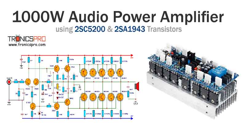
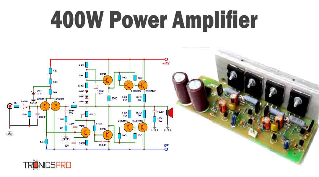
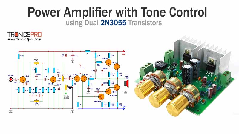
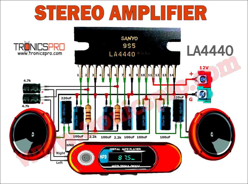
More Circuit Layouts





Components List of 600W Audio Amplifier Circuit using 2SC5200 & 2SA1943
Following is the list of all components used in this project:
- 2SC5200 Transistor x 6
- 2SA1943 Transistor x 6
- MJE340 Transistor x 1
- MJE350 Transistor x 1
- MPSA42 Transistor x 1
- MPSA92 Transistor x 3
- 2N5551 Transistor x 4
- 1N4148 Diode x 5
Explanation of 600W Audio Amplifier Circuit using 2SC5200 & 2SA1943
The 600W audio power amplifier circuit diagram is a class AB amplifier design that is capable of delivering high power while maintaining efficiency. The 2SC5200 and 2SA1943 transistors are used in the output section to handle the high power output. These transistors have a maximum collector current of 15A and a maximum collector-emitter voltage of 230V, making them ideal for high-power audio amplification.
In the driver and preamplifier sections, transistors like MJE340, MJE350, MPSA42, MPSA92, and 2N5551 are used to provide the necessary amplification and control signals to drive the output transistors. These transistors are chosen for their high gain and low noise characteristics, ensuring that the audio signal remains clear and undistorted throughout the amplification process.
Conclusion:
In conclusion, the 600W audio power amplifier circuit diagram using 2SC5200 & 2SA1943 in the output section and MJE340, MJE350, MPSA42, MPSA92, 2N5551 in the driver and preamplifier sections is a high-quality amplifier that delivers clear and powerful sound. With the use of premium components, this amplifier ensures that the audio output is distortion-free and suitable for a variety of events and gatherings.
More projects, You may like:
- Video Transmitter DIY Homemade FM Radio Transmitter
- Adjustable Power Supply DIY Battery Charger
- 12V-220V 500 Watt inverter DIY Homemade
- MPPT Solar Charge Controller DIY Homemade
- DIY LA4440 bass amplifier homemade
For more project and circuit diagrams, you can go through the Schematics in the main menu where you can find many interesting projects and circuit diagrams like audio amplifier circuits, voltage booster circuit, battery charger circuit and timer circuits etc., which are all beginner circuit projects. Feel free to check them out!


Thank you for visiting the article.





Hola cómo estás, gracias por compartir este contenido. Hice un prototipo del esquema pero tiene algún tipo de error, no funciona, podría decirme que hay que corregir en el diagrama.
Muchas gracias de antemano.
Hola buen día cómo estás, gracias por compartir este contenido. Hice un prototipo del esquema pero tiene algún tipo de error, no funciona, podría decirme que hay que corregir en el diagrama.
Muchas gracias de antemano.