


Introduction
In the world of audio amplification, power is the key. When it comes to creating impressive sound systems, a powerful amplifier is a must. One such amplifier that stands out is the 500W amplifier circuit diagram D1047 4558 presented here is a powerful audio amplifier design capable of delivering high-quality sound output. This circuit utilizes five pairs of 2SD1047 and 2SB817 transistors in the output stage, along with one pair of 2SD718 and 2SB688 transistors in the driver stage. Additionally, the pre-amplifier stage features the widely-used 4558 IC. With the appropriate implementation of these components, this amplifier circuit promises to provide an impressive 500W power output for enriching audio experiences.
This circuit packs a punch, delivering high-quality audio with immense power. In this article, we will dive into the specifications of the D1047 and B817 transistors, the 4558 IC, and discuss the working principle of this outstanding amplifier circuit.
Specifications of D1047 Transistor:
The D1047 transistor is a high voltage, NPN power amplifier transistor that is designed for audio applications. It is capable of handling up to 140 volts of voltage and currents up to 12 amperes. With a power dissipation rating of 150 watts, this transistor can comfortably handle the power requirements of the 500W amplifier circuit. Its frequency response is optimized for audio signals, making it an excellent choice for high-fidelity sound applications.
Specifications of B817 Transistor:
The B817 transistor is a PNP power amplifier transistor that complements the D1047 transistor in the 500W amplifier circuit. It is also designed for audio amplification, and its maximum voltage rating is 140 volts, similar to the D1047. However, it can handle slightly higher currents, with a maximum rated current of 8 amperes. With a power dissipation rating of 20 watts, the B817 transistor provides efficient and reliable amplification for the circuit.
Specifications of 4558 IC:
The 4558 is a dual operational amplifier IC that plays a crucial role in the 500W amplifier circuit. This IC is widely used in audio applications due to its excellent performance and reliability. It features a high slew rate, low noise, and low distortion, making it ideal for audio signal processing. The 4558 IC provides the necessary gain, stability, and overall signal integrity in the amplifier circuit, ensuring optimal performance and clear sound reproduction.
Amplifier Circuit Diagram using D1047 & 4558 IC
This project can be built using a few basic components. The circuit diagram of this project is shown below.


More Circuit Layouts


Components List of Amplifier Circuit Diagram D1047 & 4558 IC
Following is the list of all components used in this project:
- 2SD1047 Transistor x 5
- 2SB817 Transistor x 5
- 2SD718 Transistor x 1
- 2SB688 Transistor x 1
- 4558 IC x 1
- 0.22R/5W Resister x 10
- 220R/2W Resister x 4
- 100k Resister x 1
- 1k Resister x 4
- 10R/2W Resister x 2
- 10k Resister x 1
- 6.8k Resister x 1
- 47k Resister x 1
- 4.7uF Capacitor x 1
- 1uF Capacitor x 1
- 220uF Capacitor x 1
- 100nF Capacitor x 1
- 6uH Coil x 1
- +/-50V Power Supply
Explanation of Amplifier Circuit Diagram D1047 & 4558 IC
The functioning of this amplifier circuit involves the collaboration of various components. The 500W amplifier circuit operates on the principle of Class AB amplification.The D1047 and B817 transistor pairs, incorporated into the output stage, are renowned for their ability to handle high power loads efficiently. These transistors are responsible for amplifying the signal received from the driver stage, consisting of D718 and B688 transistors. The driver stage is essential for providing the necessary input for the output stage to drive the loudspeakers effectively.
The key to the formidable power of this circuit lies in the parallel arrangement of the D1047 and B817 transistor pairs. This configuration allows the amplifier to handle higher currents while maintaining stability and preventing thermal overload. The power supply should be designed to provide sufficient voltage and current to meet the requirements of the circuit.
Furthermore, the pre-amplifier stage in this circuit is powered by the 4558 IC, a widely-used integrated circuit known for its excellent audio performance. The JRC4558 IC assists in the pre-amplification stage, amplifying and shaping the audio signals before they are passed to the power amplifier stage.The pre-amplifier stage plays a crucial role in boosting the signal strength and enhancing the overall audio quality.
Conclusion
In conclusion, the 500W amplifier circuit diagram, featuring five pairs of D1047 and B817 transistors in the output stage, one pair of D718 and B688 transistors in the driver stage, and the 4558 IC in the pre-amplifier stage, offers an exceptional audio amplification solution. With its ability to provide a whopping 500W power output, this circuit design ensures a high-quality sound experience. The 4558 IC adds clean amplification and signal integrity to the circuit. By effectively utilizing the strengths of each component, this amplifier circuit promises to deliver enhanced audio performance, making it a valuable choice for various audio applications.
More projects, You may like:
- Video Transmitter DIY Homemade FM Radio Transmitter
- Adjustable Power Supply DIY Battery Charger
- 12V-220V 500 Watt inverter DIY Homemade
- 12V-220V H-Bridge Inverter DIY Homemade
- MPPT Solar Charge Controller DIY Homemade
- 18650 battery bank free charge protection module
- D718 B688 Bass Amplifier Homemade DIY
- C5200 Bass Amplifier DIY Homemade with Volume
- DIY LA4440 bass amplifier homemade
- C5200 A1943 TDA2030 Amplifier DIY Homemade
For more project and circuit diagrams, you can go through the Schematics in the main menu where you can find many interesting projects and circuit diagrams like audio amplifier circuits, voltage booster circuit, battery charger circuit and timer circuits etc., which are all beginner circuit projects. Feel free to check them out!
Thank you for visiting the article.
You may also like:
![500W MOSFET Amplifier Cercuit using 2SK1530 & 2SJ201]()
500W MOSFET Amplifier Cercuit Diagram using 2SK1530 & 2SJ201
![1400W Audio Power Amplifier Circuit using 2SC2912 & 2SA1216]()
1400W Audio Power Amplifier Circuit Diagram using 2SC2922 & 2SA1216
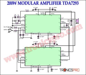
![200W Modular Amplifier TDA7293 Circuit Diagram]()
200W Modular Amplifier TDA7293 Circuit Diagram
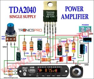
![30W TDA2040 Power Amplifier Circuit Diagram]()
30W TDA2040 Power Amplifier Circuit Diagram
![Digital Audio High-end Oscillator Circuit]()
Digital Audio High-end Oscillator Circuit
![Stepper Motor Control Circuit Diagram]()
Stepper Motor Control Circuit Diagram
![15W Power Amplifier Circuit Diagram]()
15W Power Amplifier Circuit Diagram
![100W HiFi Amplifier Circuit using 2SC3280 Transistors]()
100W HiFi Amplifier Circuit Diagram using 2SC3280 Transistors


I like the circuits
this circuit is not working.
please mark some important voitage to check the circuit
not working. i wondered how can 4558 handles -/+50v. next time u better come back with tested circuits .good luck..
The circuit itself appears to be perfect in all aspects but like usual the output transistor power banks are wired correctly but the driver for these power banks are also wired in parallel with the power opt transistor whereas the emitter should have driven the base of these transistors that wasn’t the case, I hope I’m mistaken but I think there is some error over here.
I noticed. You’re right