


Introduction
The 300W OCL power amplifier circuit diagram using 2N3055 and MJ2955 is a popular choice for audio enthusiasts looking to enhance their audio experience. This circuit utilizes the reliable and powerful 2N3055 and MJ2955 transistors in the output section, along with BC507, D313, D438, and A564 transistors in the driver and preamplifier sections. This article will provide a detailed overview of the circuit diagram, along with specifications of the transistors used.
Specifications of Transistors:
- 2N3055 transistor:
- NPN power transistor
- Maximum collector current: 15A
- Maximum collector-emitter voltage: 70V
- Maximum power dissipation: 115W
- MJ2955 transistor:
- PNP power transistor
- Maximum collector current: 15A
- Maximum collector-emitter voltage: 70V
- Maximum power dissipation: 115W
- BC507 transistor:
- NPN low noise transistor
- Maximum collector current: 100mA
- Maximum collector-emitter voltage: 45V
- Maximum power dissipation: 625mW
- D313 transistor:
- NPN power transistor
- Maximum collector current: 10A
- Maximum collector-emitter voltage: 160V
- Maximum power dissipation: 100W
- D438 transistor:
- PNP power transistor
- Maximum collector current: 5A
- Maximum collector-emitter voltage: 60V
- Maximum power dissipation: 40W
- A564 transistor:
- PNP epitaxial silicon transistor
- Maximum collector current: 7A
- Maximum collector-emitter voltage: 120V
- Maximum power dissipation: 70W
Circuit Diagram of
This project can be built using a few basic components. The circuit diagram of this project is shown below.


Caution: Website contains information on high voltage circuits. Proceed at your own risk, ensuring proper knowledge and precautionary measures to prevent electric shock or injury.
More Circuit Layouts


Components List of 300W OCL Amplifier Circuit using 2N3055 MJ2955
Following is the list of all components used in this project:
Transistors:
- 2N3055 NPN Transistor x 2
- MJE2955 PNP Transistor x 2
- D313 NPN Transistor x 1
- B507 NPN Transistor x 1
- D438 PNP Transistor x 1
- A564 PNP Transistor x 3
Resisters:
- 0.5/5W Resister x 4
- 100k Resister x 1
- 30k Resister x 2
- 560 Resister x 2
- 10k Resister x 1
- 1k Resister x 1
- 2.2k Resister x 1
- 4.7k Resister x 1
- 100 Resister x 3
- 300 Resister x 2
Capacitors:
- 100nF Capacitor x 3
- 47uF/50V Capacitor x 4
- 100pF Capacitor x 1
Miscellaneous:
- 1N4148 Diode x 5
- 45V Symmetrical Power Supply
Explanation of 300W OCL Amplifier Circuit using 2N3055 MJ2955
The 300W OCL power amplifier circuit diagram utilizing 2N3055 and MJ2955 transistors is designed to deliver a high-quality audio output with sufficient power for various audio applications. The circuit utilizes a class AB output configuration with two 2N3055 transistors and two MJ2955 transistors, providing a combined power output of 300W.
The preamplifier section of the circuit employs the BC507 transistor, a low noise NPN transistor known for its excellent performance in audio applications. This transistor ensures a clean and accurate audio signal at the input stage.
The driver section of the amplifier circuit uses the D313, D438, and A564 transistors. The D313 transistor, an NPN power transistor, acts as a voltage amplifier, while the D438 transistor, a PNP power transistor, serves as a current amplifier. The A564 transistor, a PNP epitaxial silicon transistor, is utilized for the driver stage to provide excellent signal amplification and stability.
Conclusion
The 300W OCL power amplifier circuit diagram utilizing 2N3055 and MJ2955 transistors in the output section, along with BC507, D313, D438, and A564 transistors in the driver and preamplifier sections, offers excellent audio performance and sufficient power output. The combination of these transistors ensures clean and accurate audio reproduction. Whether you are a music lover or an audio professional, this amplifier circuit will undoubtedly enhance your audio experience.
More projects, You may like:
- Video Transmitter DIY Homemade FM Radio Transmitter
- Adjustable Power Supply DIY Battery Charger
- 12V-220V 500 Watt inverter DIY Homemade
- MPPT Solar Charge Controller DIY Homemade
- DIY LA4440 bass amplifier homemade
For more project and circuit diagrams, you can go through the Schematics in the main menu where you can find many interesting projects and circuit diagrams like audio amplifier circuits, voltage booster circuit, battery charger circuit and timer circuits etc., which are all beginner circuit projects. Feel free to check them out!

Thank you for visiting the article.
You may also like:
![Simple Variable Power Supply Circuit Diagram]()
Simple Variable Power Supply DIY Circuit Diagram
![Variable Power Supply Circuit using LM337]()
Adjustable Power Supply Circuit using LM337
![STK4141 Stereo Amplifier Circuit Diagram 50W]()
STK4141 Stereo Amplifier Circuit Diagram
![2N3055 Mono Amplifier with Bluetooth Circuit Diagram]()
2N3055 Mono Amplifier with Bluetooth Circuit
![TDA2611 Audio Power Amplifier Circuit Diagram]()
TDA2611 Audio Power Amplifier Circuit Diagram
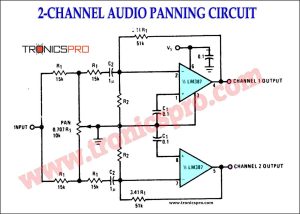
![2-Channel Audio Panning Circuit Diagram]()
2-Channel Audio Panning Circuit Diagram
![Simple Audio Amplifier Circuit using TIP41 TIP42 & TLE2141C]()
Simple Audio Amplifier Circuit Diagram using TIP41 TIP42 & TLE2141C
![200W Amplifier Circuit Diagram using Sanken 2SC2922 & 741 IC]()
200W Amplifier Circuit Diagram using Sanken 2SC2922 & 741 IC


Do you have the pcb layout for your circuits.
That would be of great benefit.