

Introduction
A bass amplifier is an essential component for any musician who wants to captivate an audience with a deep and powerful sound. To achieve this, a circuit diagram with high-quality transistors and integrated circuits is crucial. In this article, we will discuss a 200W bass amplifier circuit diagram that utilizes NJW21194 and NJW21193 transistors in the output section, C2073 and A940 transistors in the driver section, and a 4558 IC in the preamplifier section. These components combine to create a robust and efficient amplifier that will enhance the bass tones to new levels. So let’s dive into the specifications and features of these components in detail.
Specifications – NJW21194 Transistor:
- Power Output: 200W
- Voltage Rating: 230V
- Current Rating: 15A
- Collector-Emitter Voltage: 140V
- Collector Current: 15A
- Power Dissipation: 200W
- Operating Temperature: -65°C to 150°C
- Package Type: TO-3P
Specifications – NJW21193 Transistor:
- Power Output: 200W
- Voltage Rating: 230V
- Current Rating: 15A
- Collector-Emitter Voltage: 140V
- Collector Current: 15A
- Power Dissipation: 200W
- Operating Temperature: -65°C to 150°C
- Package Type: TO-3P
Specifications – 4558 IC:
- Number of Op-Amps: 2
- Input Voltage Range: ±22V
- Supply Voltage: ±18V
- Slew Rate: 1V/µs
- Bandwidth: 3MHz
- Input Bias Current: 150nA
- Package Type: DIP-8
200W Bass Amplifier Circuit Diagram using NJW21194
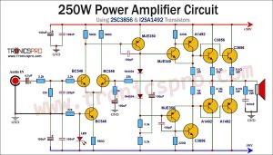
This project can be built using a few basic components. The circuit diagram of this project is shown below.

Power Supply of 200W Bass Amplifier Circuit

Caution: Website contains information on high voltage circuits. Proceed at your own risk, ensuring proper knowledge and precautionary measures to prevent electric shock or injury.
More Circuit Layouts


Components List of 200W Bass Amplifier Circuit using NJW21194
Following is the list of all components used in this project:
Transistors:
- NJW21193G Transistor x 1
- NJW21194G Transistor x 1
- 2SC2073 Transistor x 1
- 2SA940 Transistor x 1
- 4558 ic x 1
Resisters:
- 10Ω/1W Resister x 1
- 0.22Ω/5W Resister x 2
- 100Ω Resister x 1
- 100Ω/1W Resister x 2
- 150Ω/1W Resister x 2
- 1K Resister x 1
- 1K5 Resister x 2
- 2k2 Resister x 2
- 4K7 Resister x 2
- 15k Resister x 4
- 100K Resister x 1
- 150K Resister x 1
Capacitors:
- 102J Capacitor x 1
- 0.1µF Capacitor x 1
- 33pF Capacitor x 1
- 4.7µF Capacitor x 2
- 47µF Capacitor x 3
Miscellaneous:
- 50k Potentiometer x 1
- Aluminum heatsink
- Mica insulation pad
- ±45V Power Supply
Explanation of 200W Bass Amplifier Circuit using NJW21194
The NJW21194 and NJW21193 transistors are specifically designed for high-power audio amplifier applications. With a power output rating of 200W, these transistors are capable of delivering strong and clear bass tones. They feature a voltage rating of 230V and a current rating of 15A, ensuring they can handle the power requirements without any issues. The collector-emitter voltage is 140V, allowing for a wide range of input signals. Additionally, the operating temperature range of -65°C to 150°C ensures reliable performance even in challenging environments.
The 4558 IC is a dual operational amplifier that is commonly used in audio amplifier circuits. With two op-amps integrated into a single package, it offers versatility and convenience. It has a wide input voltage range of ±22V, allowing for greater signal amplification without distortion. The slew rate of 1V/µs ensures a fast response time, allowing for accurate reproduction of bass frequencies. The 3MHz bandwidth guarantees that no high-frequency details are lost. Overall, the 4558 IC provides excellent performance in the preamplifier section of the bass amplifier circuit.
Conclusion of 200W Bass Amplifier Circuit using NJW21194
In conclusion, the 200W bass amplifier circuit diagram utilizing NJW21194 and NJW21193 transistors in the output section, along with C2073 and A940 transistors in the driver section, and the 4558 IC in the preamplifier section, offers high-quality sound reproduction and ample power for bass enthusiasts. The NJW21194 and NJW21193 transistors boast impressive power handling capabilities and ensure optimal performance. The 4558 IC, with its dual op-amp design, provides excellent amplification and accurate signal reproduction. With the combination of these components, musicians can expect a bass amplifier that delivers deep, powerful, and distortion-free bass tones. So, elevate your bass playing experience with this remarkable 200W bass amplifier circuit diagram.
More projects, You may like:
- Video Transmitter DIY Homemade FM Radio Transmitter
- Adjustable Power Supply DIY Battery Charger
- 12V-220V 500 Watt inverter DIY Homemade
- MPPT Solar Charge Controller DIY Homemade
- DIY LA4440 bass amplifier homemade
For more project and circuit diagrams, you can go through the Schematics in the main menu where you can find many interesting projects and circuit diagrams like audio amplifier circuits, voltage booster circuit, battery charger circuit and timer circuits etc., which are all beginner circuit projects. Feel free to check them out!

Thank you for visiting the article.
You may also like:
 1600W MOSFET Power Amplifier Circuit Diagram using IRFP240
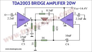
- TDA2003 Bridge Amplifier 20W circuit - Tronicspro
- 100W HiFi Amplifier Circuit Diagram using 2SC3280 Transistors
- LA4440 Stereo Amplifier Circuit Diagram
- DC Detector Circuit Diagram - Tronicspro
- 150W Audio Amplifier Circuit Diagram using Dual 2N3055 Transistors
- Power Inverter Circuit Diagram using 7473 IC
- Water Leakage Detector Circuit Diagram


Hola Quisiera saber si me pueden pasar el diseño del pcb de este amplificador de 200w