Introduction
Audio power amplifiers are essential components in any audio system, as they boost the electrical signals from audio sources to a level that can drive speakers and produce high-quality sound. Among the various types of amplifiers available, MOSFET amplifiers are widely used due to their efficiency and excellent audio performance. In this article, we will discuss a 150W MOSFET audio power amplifier circuit diagram that utilizes 2SK133 and 2SJ48 MOSFETs in the output section, along with 2SB716, 2SD756, and a pair of 2SA872A transistors in the driver and preamp sections.
Specifications of 2SK133 and 2SJ48 MOSFETs:
- 2SK133: This MOSFET has a maximum current rating of 9A and can handle a power dissipation of up to 100W. It offers a low on-resistance and is capable of operating at high temperatures, making it suitable for power amplification applications.
- 2SJ48: The 2SJ48 MOSFET also has a maximum current rating of 9A and can handle a power dissipation of up to 100W. It offers a low on-resistance and has excellent linearity, ensuring accurate audio reproduction.
Let’s examine why MOSFETs are preferred over bi-polar transistors. One advantage of MOSFETs is their thermal performance. Unlike bi-polar transistors, MOSFETs exhibit a negative temperature coefficient, meaning that as they heat up during use, the Drain-Source current decreases due to increasing internal resistance. This decrease in current causes the device temperature to reduce, which then leads to an increase in Drain-Source current. Bi-polar transistors, on the other hand, have a positive temperature coefficient, meaning that as they heat up, the collector current increases, which can lead to thermal runaway and potentially destroy the transistor.
150W MOSFET Amplifier Circuit Diagram
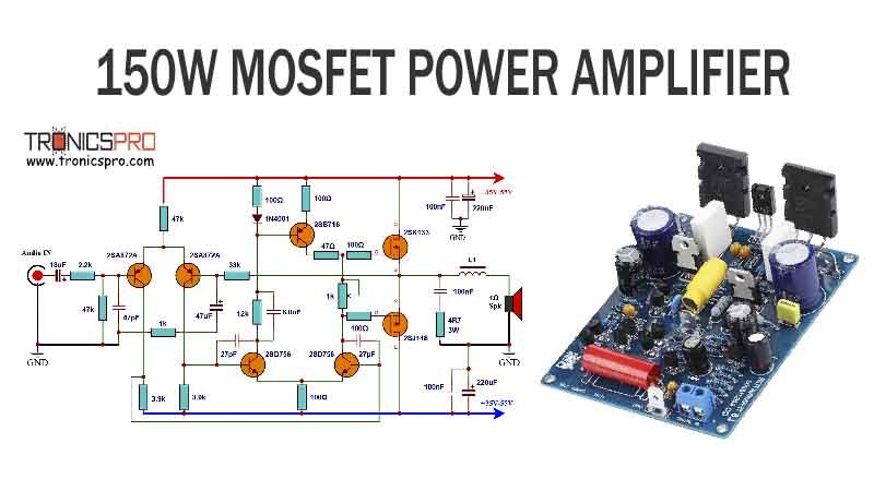
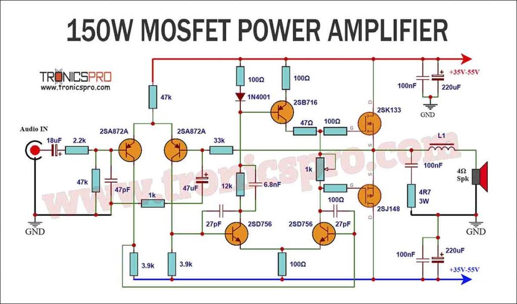
This project can be built using a few basic components. The circuit diagram of this project is shown below.
More Circuit Layouts





PCB Layouts
Components List of 150W MOSFET Amplifier Circuit
Following is the list of all components used in this project:
- 2SK133 MOSFET x 1
- 2SJ48 MOSFET x 1
- 2SB716 Transistor x 1
- 2SD756 Transistor x 2
- 2SA872A Transistor x 2
- 2.2k Resister x 1
- 47k Resister x 2
- 1k Resister x 1
- 100 Ohm Resister x 5
- 3.9k Resister x 2
- 33k Resister x 1
- 12k Resister x 1
- 47 Ohm Resister x 1
- 4.7 Ohm/3W Resister x 1
- 18uF Capacitor x 1
- 47pF Capacitor x 1
- 27pF Capacitor x 2
- 47uF Capacitor x 1
- 6.8nF Capacitor x 1
- 100nF Capacitor x 3
- 220uF Capacitor x 2
- 1N4001 Diode x 1
Working Explanation of 150W MOSFET Amplifier Circuit
The 150W MOSFET audio power amplifier circuit offers an efficient and robust amplification solution for audio enthusiasts. The key components used in this circuit are the 2SK133 and 2SJ48 MOSFETs, which provide excellent power handling capabilities and low distortion characteristics.
The preamplifier section of the amplifier is constructed using a pair of 2SA872A transistors, ensuring a high input impedance and low noise operation. These transistors efficiently amplify the weak audio signals, delivering them to the driver section for further amplification.
The driver section of the amplifier employs 2SB716 and 2SD756 transistors, which provide sufficient current gain and power handling capabilities. These transistors amplify the signal received from the pre-amplifier section and drive the output MOSFETs efficiently.
The output section consists of the 2SK133 and 2SJ48 MOSFETs, which serve as the power amplifiers in this circuit. These MOSFETs are known for their high current and power capabilities, making them suitable for driving speakers with ease. The output section is designed to handle high wattage requirements, ensuring a clean and detailed audio output.
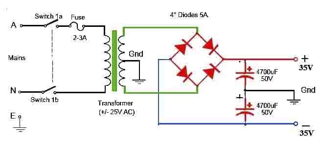
For powering the amplifier, a split rail supply is necessary. This supply should have two secondary windings with a voltage rating of 39V-0-39V. Once the power supply unit (PSU) is activated, each supply rail will develop a DC voltage of 55V-58V. It is crucial to note that this voltage range is the absolute maximum allowed for the MOSFET used. To prevent component breakdown, it is essential not to exceed the specified maximum voltage given for the chosen PSU.
When selecting a loudspeaker, it is important to ensure that it can handle continuous power levels of 100 watts RMS or more for 8 ohm versions, and 150-200 watts for 4 ohm versions.
Conclusion
The 150W MOSFET audio power amplifier circuit diagram presented in this article demonstrates the utilization of high-quality components to achieve excellent audio performance and power handling capabilities. The 2SK133 and 2SJ48 MOSFETs in the output section, along with the 2SB716, 2SD756, and 2SA872A transistors in the driver and preamp sections, ensure efficient amplification with minimal distortion.
By utilizing this circuit, audio enthusiasts can enjoy high-quality sound reproduction with sufficient power to drive speakers. The combination of these carefully selected components offers a reliable and efficient solution for audio amplification needs.
More projects, You may like:
- Video Transmitter DIY Homemade FM Radio Transmitter
- Adjustable Power Supply DIY Battery Charger
- 12V-220V 500 Watt inverter DIY Homemade
- 12V-220V H-Bridge Inverter DIY Homemade
- MPPT Solar Charge Controller DIY Homemade
- 18650 battery bank free charge protection module
- D718 B688 Bass Amplifier Homemade DIY
- C5200 Bass Amplifier DIY Homemade with Volume
- DIY LA4440 bass amplifier homemade
- C5200 A1943 TDA2030 Amplifier DIY Homemade
For more project and circuit diagrams, you can go through the Schematics in the main menu where you can find many interesting projects and circuit diagrams like audio amplifier circuits, voltage booster circuit, battery charger circuit and timer circuits etc., which are all beginner circuit projects. Feel free to check them out!

Thank you for visiting the article.


