

Introduction
A powerful bass amplifier is an essential component for any musician or music enthusiast who wants to enhance their bass sound. The 100W Bass Amplifier Circuit Diagram using 2N3055 & MJ2955 we are going to discuss in this article will allow you to achieve that, using high-quality transistors in each section.
The output section of this amplifier circuit features the renowned 2N3055 and MJ2955 NPN and PNP transistors. These transistors are both known for their excellent power handling capabilities, making them ideal for creating a powerful bass sound. The driver section utilizes BD139, BD140, BC546, and BC556 transistors, which provide the necessary amplification and control for the signal. Lastly, the preamplifier section employs BC560 transistors to shape and enhance the bass tone before it reaches the output stage.
Specification of Transistors:
- 2N3055:
- Maximum Power Dissipation: 115W
- Collector-Base Voltage: 60V
- Collector-Emitter Voltage: 70V
- DC Current Gain: 20-70
- Transition Frequency: 3MHz
- MJ2955:
- Maximum Power Dissipation: 115W
- Collector-Base Voltage: 60V
- Collector-Emitter Voltage: 70V
- DC Current Gain: 20-70
- Transition Frequency: 2MHz
- BD139:
- Maximum Power Dissipation: 8W
- Collector-Base Voltage: 80V
- Collector-Emitter Voltage: 80V
- DC Current Gain: 40-160
- Transition Frequency: 40MHz
- BD140:
- Maximum Power Dissipation: 8W
- Collector-Base Voltage: 80V
- Collector-Emitter Voltage: 80V
- DC Current Gain: 40-160
- Transition Frequency: 40MHz
Bass Amplifier Circuit Diagram using 2N3055 & MJ2955
This project can be built using a few basic components. The circuit diagram of this project is shown below.


More Circuit Layouts


Components List of Bass Amplifier Circuit using 2N3055 & MJ2955
Following is the list of all components used in this project:
Transistors:
- 2N3055 or (TIP3055/TIP35) NPN Transistor x 1
- MJ2955 or (TIP2955/TIP36) PNP Transistor x 1
- BD139 NPN Transistor x 1
- BD140 PNP Transistor x 1
- BC546 NPN Transistor x 1
- BC556 PNP Transistor x 2
- BC560C PNP Transistor x 2
Resisters:
- 18K Resistor x 1
- 3.9K Resistor x 1
- 1K Resistors x 2
- 2.2K Resistor x 1
- 15K Resistor x 1
- 22K Resistor x 1
- 330R Resistor x 1
- 10R Resistors x 2
- 47R 5W Resistors x 2
- 10R – 2W Resistor x 1
Capacitors:
- 1µF Capacitor x 1
- 470pF Capacitor x 1
- 47µF Capacitor x 1
- 15pF Capacitor x 1
- 220nF Capacitor x 1
- 100nF Capacitor x 1
Miscellaneous:
- 1N4148 Diodes x 4
- ±35V Symmetrical Power Supply
- 4Ω Speaker
Explanation of Bass Amplifier Circuit using 2N3055 & MJ2955
By using the transistors and following the circuit diagram, you can create a bass amplifier that not only provides exceptional power but also delivers crystal-clear sound with deep bass tones. So, get your components together and build your 100W Bass Amplifier with confidence knowing it will provide an impressive performance for all your bass playing needs.
Conclusion
With the 100W Bass Amplifier Circuit Diagram using 2N3055 & MJ2955 described above, you can build a powerful and high-quality bass amplifier that will greatly enhance your bass sound. The combination of 2N3055 and MJ2955 transistors in the output section ensures ample power handling, allowing you to crank up the volume without sacrificing quality. The driver section, utilizing BD139, BD140, BC546, and BC556 transistors, delivers the necessary amplification and control for optimal sound reproduction. Lastly, the BC560 transistors in the preamplifier section shape and enhance the bass tone, providing a well-rounded and defined sound.
More projects, You may like:
- Video Transmitter DIY Homemade FM Radio Transmitter
- Adjustable Power Supply DIY Battery Charger
- 12V-220V 500 Watt inverter DIY Homemade
- MPPT Solar Charge Controller DIY Homemade
- DIY LA4440 bass amplifier homemade
For more project and circuit diagrams, you can go through the Schematics in the main menu where you can find many interesting projects and circuit diagrams like audio amplifier circuits, voltage booster circuit, battery charger circuit and timer circuits etc., which are all beginner circuit projects. Feel free to check them out!

Thank you for visiting the article.
You may also like:
![TDA2030 Amplifier Single Supply Circuit Diagram]()
TDA2030 Amplifier Single Supply Circuit Diagram
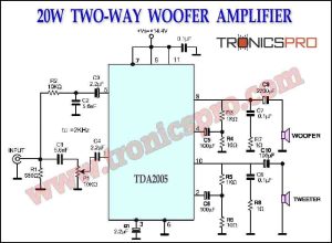
![20W Two-Way Woofer Amplifier TDA2005 Circuit Diagram]()
20W Two-Way Woofer Amplifier TDA2005 Circuit
![Tone Control Circuit Diagram]()
Tone Control Circuit Diagram OPA627 IC
![Audio Preamplifier Circuit Diagram using 2N3903]()
Audio Preamplifier Circuit Diagram using 2N3903
![400W Audio Amplifier Circuit Diagram pcb2]()
400W Power Amplifier Circuit Diagram | Audio Amplifier
![120W MOSFET Amplifier Circuit using IRFP240 & IRFP9240]()
120W MOSFET Amplifier Circuit Diagram using IRFP240 & IRFP9240
![300W Power Amplifier Circuit DIY Homemade]()
300W Power Amplifier Circuit Diagram DIY Homemade
![pulse frequency modulator circuit diagram2]()
Pulse Frequency Modulator Circuit


Esta esquema e uma treta.
A tensão de CE dos transístores de saída tem que ser maior com o mínimo de 20% do que valor de alimentação entre o braço positivo e negativo.
Uce(60V) > (35V+35V) +20%
Nao respeitando esta relação o amplificador vai queimar acima de uma potência de saída.