Introduction
An audio amplifier is an essential component in any audio system to amplify the weak signals from audio sources to drive speakers. In this article, we will discuss a 100W audio amplifier circuit diagram using TIP3055 and TIP2955 in the output section, BC546 and BC557 in the driver and preamplifier sections.
Specifications:
TIP3055:
- Maximum Power Dissipation: 90 W
- Collector-Emitter Voltage: 60 V
- Collector Current: 15 A
- Gain: 20-70
- Package: TO-218
TIP2955:
- Maximum Power Dissipation: 90 W
- Collector-Emitter Voltage: 60 V
- Collector Current: 15 A
- Gain: 20-70
- Package: TO-218
BC546:
- Collector Current: 100 mA
- Power Dissipation: 500 mW
- Hfe: 110-800
- Package: TO-92
BC557:
- Collector Current: 100 mA
- Power Dissipation: 500 mW
- Hfe: 110-800
- Package: TO-92
100W Amplifier Circuit Diagram using TIP3055 & TIP2955
This project can be built using a few basic components. The circuit diagram of this project is shown below.
Caution: Website contains information on high voltage circuits. Proceed at your own risk, ensuring proper knowledge and precautionary measures to prevent electric shock or injury.
More Circuit Layouts








Components List of 100W Amplifier Circuit using TIP3055 & TIP2955
Following is the list of all components used in this project:
- TIP3055 Transistor x 1
- TIP2955 Transistor x 1
- BC546 Transistor x 2
- BC557 Transistor x 3
- 1N4148 Diode x 2
- 0.33Ω/5W Resister x 2
- 10Ω/2W Resister x 1
- 22k Resister x 1
- 2.2k Resister x 1
- 4.7k Resister x 2
- 47k Resister x 1
- 100k Resister x 1
- 220uF Capacitor x 2
- 100nF Capacitor x 3
- 10uF Capacitor x 1
- 1uF Capacitor x 1
- 150pF Capacitor x 1
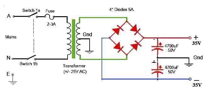
- ±35V Symmetrical Power Supply
- 4Ω Speaker
Explanation of 100W Amplifier Circuit using TIP3055 & TIP2955
The circuit diagram consists of TIP3055 and TIP2955 transistors in the output section to handle the high power output of 100W. These transistors are capable of delivering high power and have good thermal stability. In the driver section, BC546 and BC557 transistors are used to boost the weak input signal from the audio source. These transistors have high gain and are suitable for driving the output transistors.
The circuit is designed to provide a clean and powerful audio output with minimal distortion. The use of high-quality components and proper heat sinking ensures the circuit’s reliability and longevity. The overall design of the circuit is simple and easy to build, making it ideal for DIY audio enthusiasts.
Conclusion
In conclusion, the 100W audio amplifier circuit using TIP3055, TIP2955, BC546, and BC557 transistors is a reliable and efficient option for audio amplification. With its high power output and low distortion, it is suitable for driving speakers in various audio applications. By following the circuit diagram and using quality components, you can build a powerful audio amplifier for your audio system.
More projects, You may like:
- Video Transmitter DIY Homemade FM Radio Transmitter
- Adjustable Power Supply DIY Battery Charger
- 12V-220V 500 Watt inverter DIY Homemade
- MPPT Solar Charge Controller DIY Homemade
- DIY LA4440 bass amplifier homemade
For more project and circuit diagrams, you can go through the Schematics in the main menu where you can find many interesting projects and circuit diagrams like audio amplifier circuits, voltage booster circuit, battery charger circuit and timer circuits etc., which are all beginner circuit projects. Feel free to check them out!

Thank you for visiting the article.




Cual es voltaje de cada capacitor o condensador?