Introduction
Are you tired of dealing with unexpected water leaks and the costly damages they cause? Introducing a water leakage detector circuit using 555 IC! This handy device utilizes the well-known 555 timer integrated circuit to detect water present in its environment. The concept is simple: the presence of water completes a circuit, triggering an alarm to alert you before more significant damage occurs.
To build this device, you will need a few inexpensive components including a 555 timer chip, resistor, capacitor, and transistor. With basic soldering skills and some patience, constructing this DIY device is straightforward. The final result is peace of mind knowing that unexpected leaks no longer pose a threat to your home or office’s safety or budget.
Circuit Diagram
of Water Leakage Detector Circuit

More Circuit Layouts


Components List
of Water Leakage Detector Circuit
- 555 IC x 1
- BC517 Transistor x 1
- 22uf / 16V Capacitor x 1
- 10nf Capacitor x 2
- 100k Resister x 1
- 470k Resister x 1
- 4.7k Resister x 2
- Test Switch (optional)
- 10 Ohms Speaker
- 5V-15V Power Supply
Working Explanation
of Water Leakage Detector Circuit
The detector produces an audible tone when its Probes detect the presence of a conductive liquid, such Os water. It may be used as a cellar flooding alarm, or near a washing machine to give a warning immedi- ately there may be a leaking hose.
When water is detected, the probes pass a small current which causes the base potential of darlington transistor T1 to be pulled well below 0.6 V. As a result, the collector volt- age swings high, lifting the reset condition of the oscillator, which will start to work.. Conversely, if no water is detected, T1 keeps IC1 reset.
The well-known 555, IC1, is used in astable (oscillator) mode, directly driving a small loudspeaker. The alarm tone is set to a frequency of about 700Hz by network R1-R3-C1 and has a duty factor of about 0.5.
An optional push-button switch, S1, enables the circuit to be tested. When the button is pressed, the loudspeaker should sound.
Current drain of the circuit is about 10 mA when no water is detected, and about 50 mA when the alarm sounds. These values were measured with a supply voltage of 6 V.
Conclusion
n conclusion, the Water Leakage Detector Circuit using 555 IC is an effective and low-cost solution for detecting water leaks in homes and offices. By utilizing the capabilities of the reliable 555 timer integrated circuit (IC), this device can detect even small amounts of water leakage and trigger an alarm to alert users. The use of commonly available components makes it easy to build and maintain, while also allowing for customization based on individual needs. Overall, this project is a great example of how simple electronic circuits can be used to solve practical problems and improve our daily lives.
More projects, You may like:
- Video Transmitter DIY Homemade FM Radio Transmitter
- Adjustable Power Supply DIY Battery Charger
- 12V-220V 500 Watt inverter DIY Homemade
- 12V-220V H-Bridge Inverter DIY Homemade
- MPPT Solar Charge Controller DIY Homemade
- 18650 battery bank free charge protection module
- D718 B688 Bass Amplifier Homemade DIY
- C5200 Bass Amplifier DIY Homemade with Volume
- DIY LA4440 bass amplifier homemade
- C5200 A1943 TDA2030 Amplifier DIY Homemade
You may also like:
![150W Audio Amplifier Circuit Diagram using 2N3055 Transistors]()
150W Audio Amplifier Circuit Diagram using Dual 2N3055 Transistors
![200W Amplifier Circuit Diagram using Sanken 2SC2922 & 741 IC]()
200W Amplifier Circuit Diagram using Sanken 2SC2922 & 741 IC
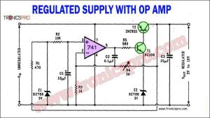
![Regulated Power Supply Circuit Diagram using Op Amp 741]()
Regulated Power Supply Circuit using Op-Amp 741
![100W Amplifier Circuit Diagram using 2N3055 and 2N2955]()
100W Amplifier Circuit Diagram using 2N3055 and 2N2955
![VU Meter Circuit Diagram One Transistor 6 LEDs]()
VU Meter Circuit Diagram One Transistor 6 LEDs
![150 Watt Lamp Dimmer Circuit Diagram]()
150 Watt Lamp Dimmer Circuit Diagram
![TDA2030 Amplifier with Tone Control Circuit Diagram]()
TDA2030 Amplifier with Tone Control Circuit Diagram
![Descrete Voltage Regulator Circuit using BD680 Transistor]()
Discrete Voltage Regulator Circuit using BD680 Transistor