Introduction
The TDA7294 is a highly reliable and high-quality audio amplifier chip that has been developed by STMicroelectronics, one of the leading semiconductor manufacturers in the world. Its reputation for providing crystal-clear audio output has made it an extremely popular choice among audio enthusiasts and professionals alike. In this article, we will discuss about TDA7294 Bridge Power Amplifier Circuit of 170 watts.
Further enhancing the TDA7294‘s reputation is the 170W Bridge Power Amplifier circuit diagram. This circuit is designed to provide more power to the amplifier and allow it to be used in larger audio setups. In this article, we will take a closer look at this circuit and explore the benefits it provides.
Circuit Diagram
of TDA7294 Bridge Power Amplifier

More Circuit Layouts


The TDA7294 Bridge Power Amplifier circuit diagram uses two TDA7294 chips to create the bridge amplifier configuration. This provides a maximum output power of 170W RMS into an 8 ohm load. The recommended power supply voltage for this amplifier is +/-35V, with a minimum current rating of 5A.
Working Explanation
of TDA7294 Bridge Power Amplifier
Understanding the TDA7294 Bridge Power Amplifier Circuit
The TDA7294 Bridge Power Amplifier circuit diagram is designed to double the output voltage and power of the TDA7294 amplifier by bridging two amplifiers together. This bridge configuration essentially allows the amplifier to operate in a higher power range, providing more audio output without causing any damage to the amplifier or speaker.
A bridge amplifier is a specialized configuration of an audio amplifier that can deliver twice the voltage and four times the power of a single amplifier. This is achieved by combining two “mirrored” amplifier circuits in a bridge configuration. Each amplifier is driven by the same audio signal but with opposite phase, effectively doubling the output voltage and current. When the positive output terminal of one amplifier is connected to the speaker, the negative output terminal of the other amp is connected to the same speaker. This effectively eliminates the need for a large center-tapped transformer as used in conventional amplifiers, resulting in a simpler and more efficient design.
The bridge configuration also provides other advantages that make it a popular choice in audio amplifiers. One of the most significant benefits is its efficiency. Compared to conventional amplifiers, bridge amplifiers can achieve much higher efficiency, resulting in less power wastage and lower operating temperatures. As a result, they are often used in high-power PA systems, professional audio setups, and in-car audio systems that require high power output.
Advantages of the TDA7294 Bridge Power Amplifier Circuit Diagram
The TDA7294 Bridge Power Amplifier circuit diagram offers several advantages that make it a popular choice among audio enthusiasts and professionals. Some of these benefits include:
High-Quality Audio Output: The TDA7294 is already known for providing high-quality audio output, but the bridge configuration of this circuit enhances this even further. By combining two amplifiers in a bridge configuration, it effectively doubles the output voltage and current, resulting in a more powerful and dynamic sound.
Greater Efficiency: The bridge configuration used in this circuit diagram provides greater efficiency compared to conventional amplifiers, resulting in less power wastage and lower operating temperatures. As a result, this amplifier is ideal for high-power applications and environments where a more efficient amplifier is required.
Simplified Design: The bridge configuration eliminates the need for a large center-tapped transformer as used in conventional amplifiers, resulting in a simpler and more efficient design. This makes it easier and more cost-effective to build, repair, and maintain.
Increased Power Output: The TDA7294 Bridge Power Amplifier circuit diagram provides a maximum output power of 170W RMS into an 8 ohm load. This is much higher than the output of a single TDA7294 chip, making it ideal for larger audio applications.
Conclusion
The TDA7294 Bridge Power Amplifier circuit diagram is an excellent choice for those looking to boost the power output of their audio amplifier without sacrificing quality or efficiency. By using two TDA7294 chips in a bridge configuration, it provides a more powerful and dynamic sound while maintaining the high-quality output that the TDA7294 is known for.
Whether you’re a home audio enthusiast, a professional sound engineer, or running a PA system, this circuit diagram provides an efficient and cost-effective solution for your high-power audio needs. With its simplified design, increased efficiency, and high-power output, it’s no wonder why it has become such a popular choice in the audio community.
More projects, You may like:
- Video Transmitter DIY Homemade FM Radio Transmitter
- Adjustable Power Supply DIY Battery Charger
- 12V-220V 500 Watt inverter DIY Homemade
- 12V-220V H-Bridge Inverter DIY Homemade
- MPPT Solar Charge Controller DIY Homemade
- 18650 battery bank free charge protection module
- D718 B688 Bass Amplifier Homemade DIY
- C5200 Bass Amplifier DIY Homemade with Volume
- DIY LA4440 bass amplifier homemade
- C5200 A1943 TDA2030 Amplifier DIY Homemade
You may also like:
 Accurate Bass Tone Control Circuit Diagram
- Water Leakage Detector Circuit Diagram
- 30W MOSFET Amplifier Circuit Diagram DIY
- Polarity Reverser Circuit Diagram - TRONICSpro
- 100W MOSFET Amplifier Circuit Diagram using 2SK134 & 2SJ49
- 800W Power Amplifier Circuit C5200 A1943
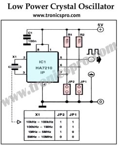
- Crystal Oscillator Low-power Circuit
- Bass Preamplifier Circuit Diagram for Subwoofer